
Method for shape classification of an object

a technology for objects and shapes, applied in the field of object shape classification, can solve the problems of deformation of a specific component, deviation of an ideal or nominal shape, and partial or complete malfunction of the final product, and achieve the effect of very flexible definition of shape categories

Active Publication Date: 2019-02-26
KLA CORP
View PDF20 Cites 0 Cited by
  • Summary
  • Abstract
  • Description
  • Claims
  • Application Information

AI Technical Summary

Benefits of technology

[0009]A general object of the present invention is to provide a method for shape classification of an object, which allows flexibly classifying objects according to user-defined categories, which may be updated or modified as required.
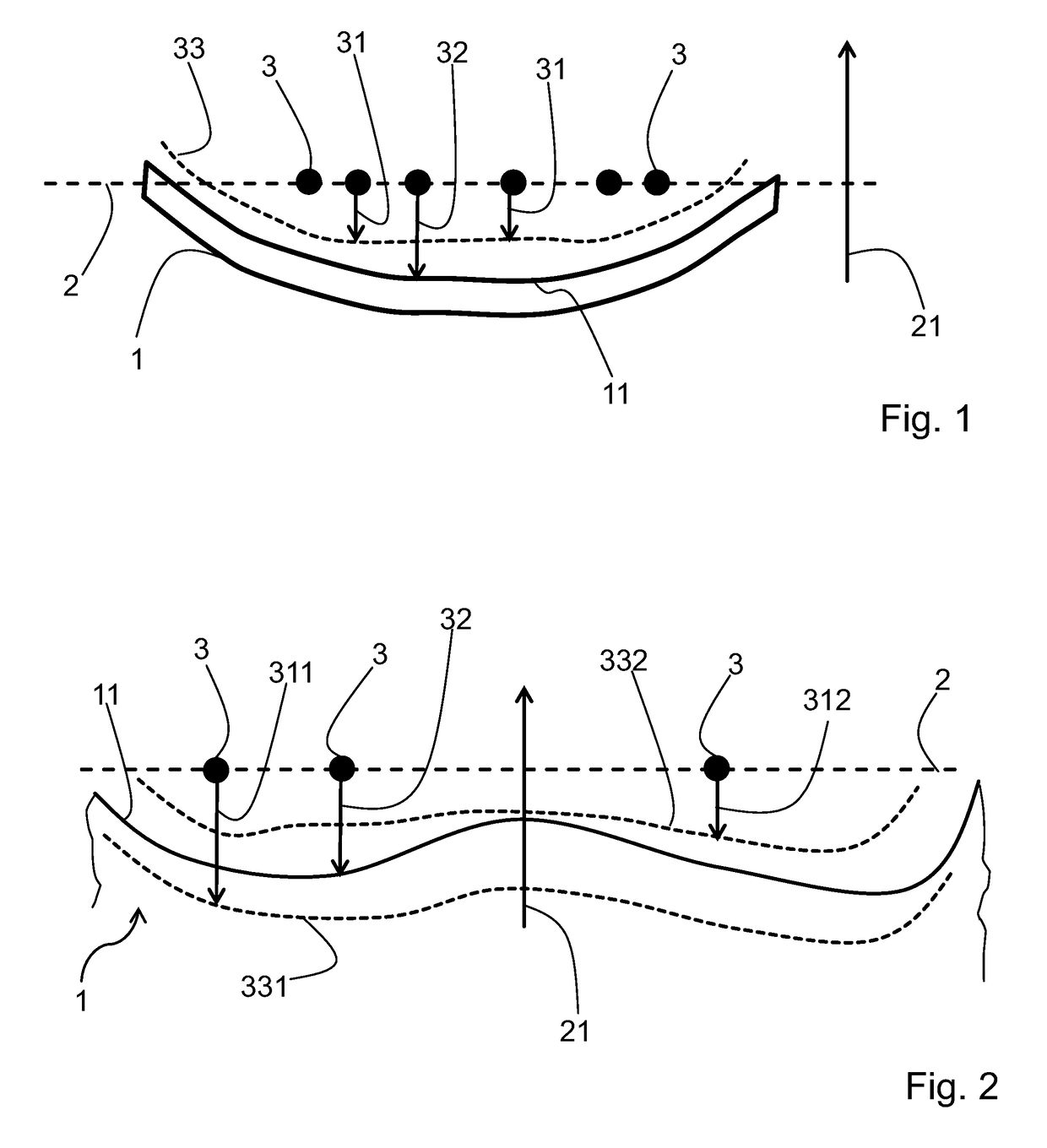
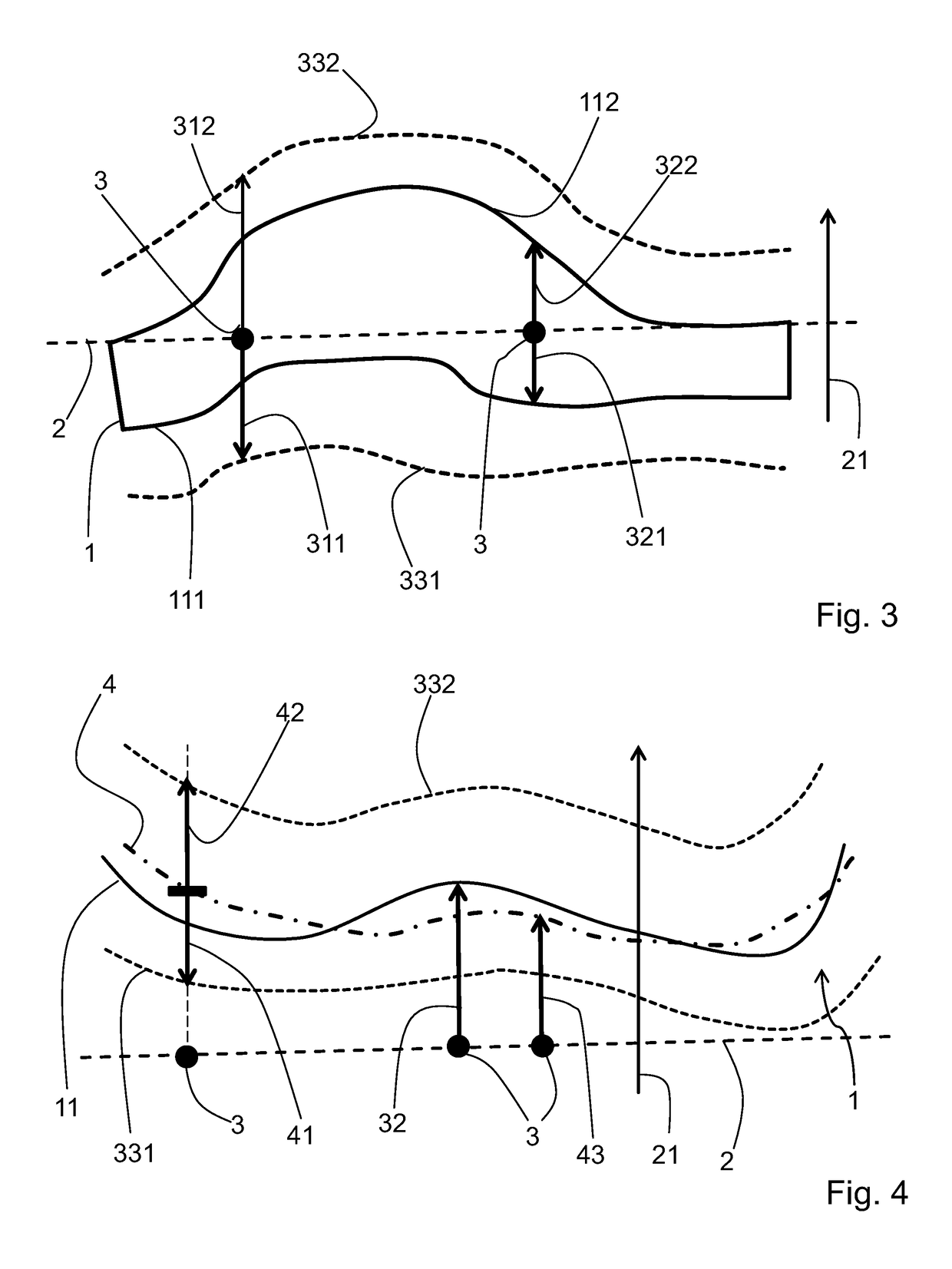
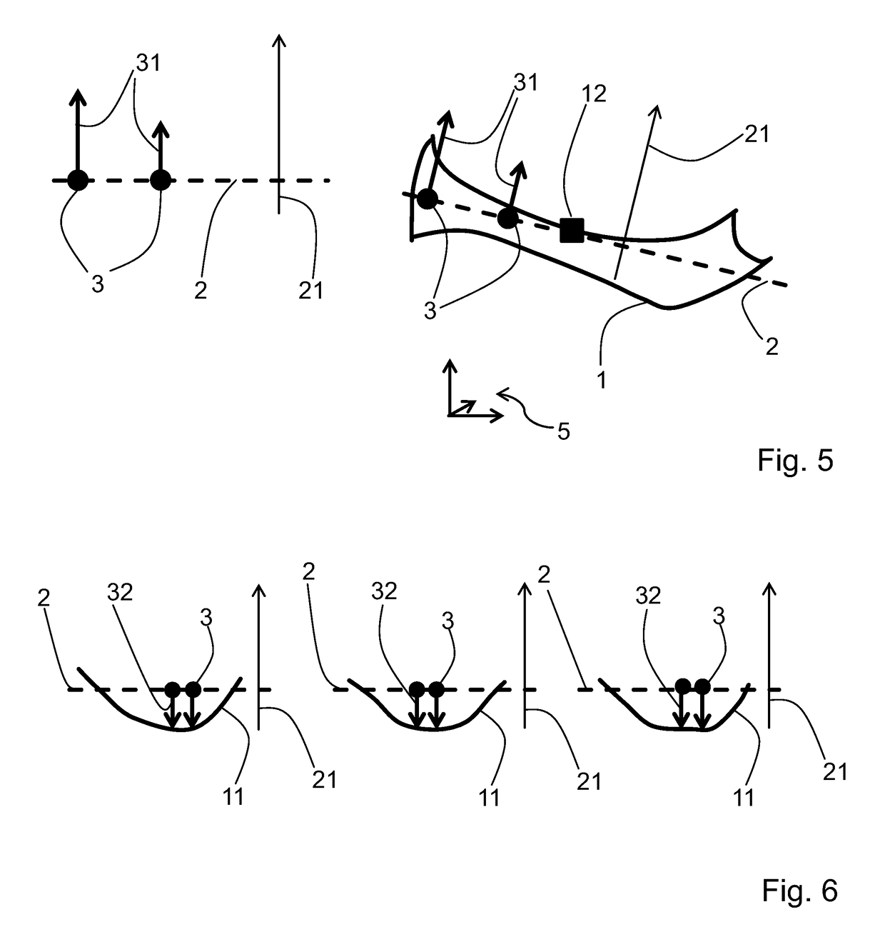
[0018]The user of the method is free to specify the defining elements of a shape category, namely the plane, points in the plane, and the boundary in terms of the limit coordinates. Therefore the method evidently is very flexible and can be easily adapted to new requirements, like new types of components or novel fashions of assembling components.
[0023]The method according to the invention allows the user to define shape categories very flexibly. A particular way of defining a shape category is to derive the defining quantities of a shape category from a set of objects which are examples of the category to be defined. One possibility for doing this is as described below.

Problems solved by technology

In such a case, it is often necessary to obtain more precise information on this shape for each individual object, as the mere knowledge of the type of object is not sufficient.
Due to, usually unavoidable, inaccuracies in manufacturing the components, each component will exhibit deviations from an ideal or nominal shape.
A further cause of such deviations is deformations of a specific component which result from mounting the component on further components, for example due to mechanical stresses.
The deviations may lead to problems in assembling the respective apparatus or device, which may lead to partial or complete malfunction of the final product.
The categories of objects possible by this approach are rather limited, and furthermore are fixed by the geometry of second order surfaces.

Method used


Image

  • Method for shape classification of an object
  • Method for shape classification of an object
  • Method for shape classification of an object

Examples


Embodiment Construction

[0039]At the outset, it should be appreciated that like reference characters on different drawing views identify identical, or functionally similar, structural elements of the invention. While the present invention is described with respect to what is presently considered to be the preferred aspects, it is to be understood that the invention as claimed is not limited to the disclosed aspect. Also, it is to be understood that the invention is not limited in its application to the details of construction and the arrangement of the components set forth in the following description or illustrated in the drawings. The invention is applicable to other embodiments or of being practiced or carried out in various ways and is intended to include various modifications and equivalent arrangements within the spirit and scope of the appended claims.

[0040]Furthermore, it is understood that this invention is not limited to the particular methodology, materials and modifications described and as suc...


PUM


Abstract

A method for shape classification of an object is provided. Shape categories are provided which specify a plane and points therein relative to the object, and also specify at least one limit coordinate for each such point, the limit coordinate defining a boundary in a direction normal to the plane for the shape of the object considered in order for the object to be classified into a respective shape category. The shape categories can be provided by a user, making the method very flexible. The shape categories can in particular be derived from a set of samples of objects representing a shape category to be defined. For classification, the position of a surface of the object is measured at each of the points defined in the shape category, and the result is compared with the corresponding limit coordinate.

Description

CROSS-REFERENCE TO RELATED APPLICATIONS[0001]This application is filed under 35 U.S.C. § 111(a) and § 365(c) as a continuation of international Patent Application No. PCT / US2015 / 045961, filed on Aug. 19, 2015, which application claims the benefit of U.S. Provisional Patent Application No. 62 / 137,650, filed on Mar. 24, 2015, which applications are incorporated herein by reference in their entireties,FIELD OF THE INVENTION[0002]The method relates to the classification of the shape of an object. An object is classified into one or plural user-defined categories depending on whether the object's shape fits between boundaries associated with each category, The object may for example be a component for an electronic device.BACKGROUND OF THE INVENTION[0003]In various fields of technology objects are handled which, though of the same type, may vary in their shape. In such a case, it is often necessary to obtain more precise information on this shape for each individual object, as the mere k...

Claims


Application Information

Patent Timeline
Patent Type & Authority Patents(United States)
IPC IPC(8): G01B21/20G06K9/00G06K9/62G01B21/30G06K9/48
CPCG01B21/20G01B21/30G06K9/6211G06K9/00214G06K2009/487G06V20/653G06V10/476G06V10/757G06V20/66
Inventor HERMANS, LAURENTDELFOSSE, ERICNIJS, FRANSTHISSEN, FRANCISDE GREEVE, JOHAN
Owner KLA CORP
Learn More