
Machine and method for the semi-continuous cold-bending of sections with low ductility

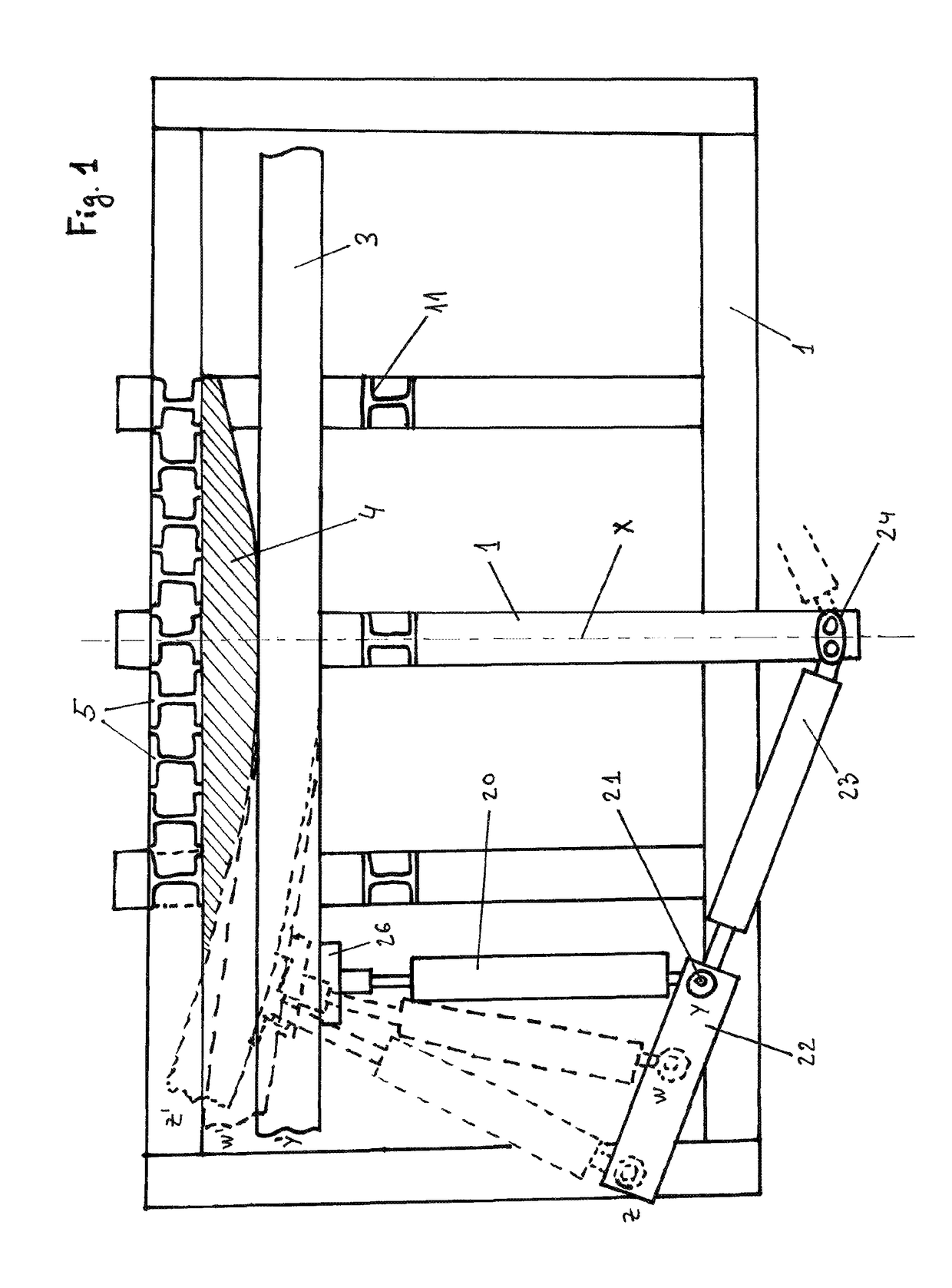
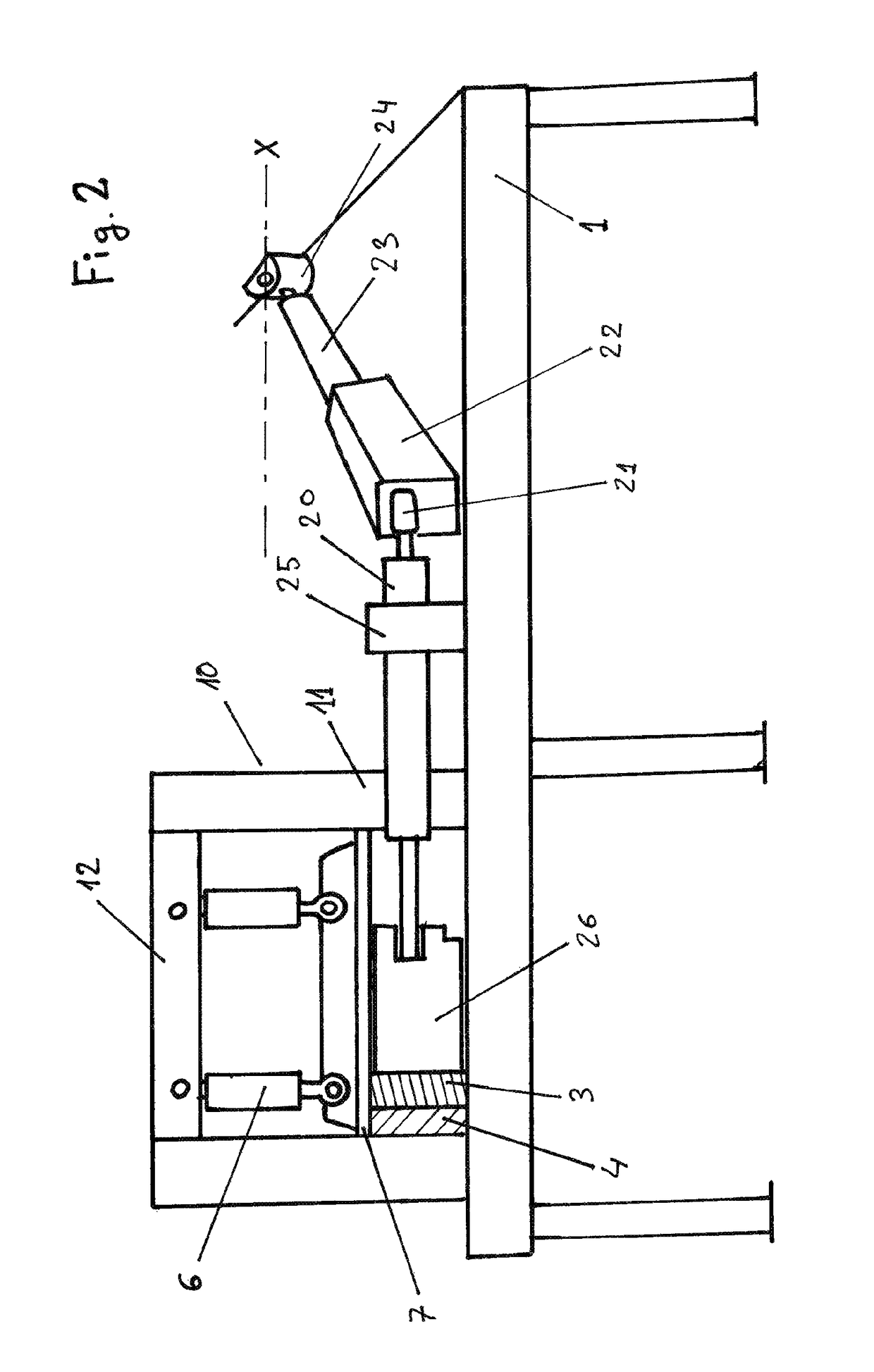
a technology of semi-continuous cold bending and cold bending, which is applied in the field of machine and method for semi-continuous cold bending of sections with low ductility, can solve the problems of not allowing semi-continuous bending, not valid machines for closed cross-section profiles, and limited use of roller bending machines for bending small or large sections of aluminium profiles or small or large sections of steel profiles

Active Publication Date: 2018-12-25
INMOTEC ASESORIA TECNICA SL
View PDF4 Cites 0 Cited by
  • Summary
  • Abstract
  • Description
  • Claims
  • Application Information

AI Technical Summary

Benefits of technology

The invention describes a machine and process for bending low-ductility materials, such as aluminum, using a vertical support and compression plate. The machine can bend profiles of any length, type, and cross-section area, ensuring consistent bending results. The invention provides a solution for manufacturing bent profiles with cold semi-continuous bending, which can be used for various applications such as tent skylights, facade profiles, and truck tarps.

Problems solved by technology

This type of roller bending machines have limited use for bending of small section aluminium profiles or small or large section steel profiles because the roller support on the profile is made only on one line (line of contact).
This type of machines are used for open profiles and of short length since they are limited in that the size of the tool that exerts the deformation must be equal to the size of the bend to be made, therefore not allowing a bend of a semi-continuous type.
Therefore, they are not valid machines for closed cross-section profiles either, since executing the two necessary forces for the process on the mentioned type of closed profile would bring to closure of the inner recess of the profile.
As the cylinder rests in the line on the profile to be bent (line of contact), the increase of stress on the profile to be bent may bring to the risk of the profile “getting stuck”.

Method used


Image

  • Machine and method for the semi-continuous cold-bending of sections with low ductility
  • Machine and method for the semi-continuous cold-bending of sections with low ductility

Examples


Embodiment Construction

[0009]The machine and method object of this invention overcomes the disadvantages of the aforementioned methods in a simple and effective manner.

[0010]It is a machine that allows different types of combinations of cold bending of aluminium profiles usually made by extrusion: semi-continuous bending, single radius bending, bending with different radiuses in different sections of the profile, or bendings of variable radius. All in aluminium profiles of any length, of open or closed type, with cross-sections inscribed in a rectangle normally of dimensions of up to 450×450 mm or equivalent, and of different lengths in a single piece of 0.25 to 30 meters.

[0011]The bent profiles can be used for tents, skylights, etc., or facade profiles, including curtain walls, as well as for sun protection slats, trirail bodywork for truck tarps, etc., guaranteeing the homogeneity of the bend in all the bent pieces, without the profile being stuck in the machine during its bending or its transversal sec...


PUM

PropertyMeasurementUnit
lengthsaaaaaaaaaa
lengthsaaaaaaaaaa
lengthaaaaaaaaaa

Abstract

The invention relates to a machine and method for the semi-continuous cold-bending of sections (3) with low ductility, of the type including a horizontal mount (1) and an interchangeable tool (4) against which the section (3) is bent. The machine includes a gantry support (10). The tool (4) is located in a zone delimited by the mount (1), vertical supports (5) for the tool (4), and a compression plate (7) actuated by vertical pressure cylinders. The tool (4) is positioned facing an actuation plane defined by a double set of hydraulic positioning (23) and push (20) cylinders. The bent sections (3) can be used for tents, skylights, facades, solar shading louvres, or three-rail frames for truck tarps, guaranteeing a uniform bend in all bent sections, without the section becoming pinned in the machine during bending.

Description

SUMMARY[0001]Machine and method for cold semi-continuous bending of low ductility profiles (3) of the type that comprises a horizontal bed (1) and an interchangeable tool (4) against which the bending of the profile (3) is generated.[0002]The machine consists of a support frame (10). The tool (4) is located in an area delimited by the bed (1), vertical supports (5) of the tool (4) and a compression plate (7) operated by vertical press cylinders. The tool (4) is located in front of an operation plane defined by a double set of positioning hydraulic cylinders (23) and a pusher (20).[0003]The bent profiles (3) can be used for tents, skylights, facade profiles, sun protection slats, or trirail bodywork for truck tarps, guaranteeing the homogeneity of the bend in all the bent profiles, without the profile being stuck in the machine during its bending.OBJECT OF THE INVENTION[0004]This invention belongs to the field of the technique of machinery and methods for semi-continuous cold bending...

Claims


Application Information

Patent Timeline
Patent Type & Authority Patents(United States)
IPC IPC(8): B21D7/06B21D7/022B21D7/024B21D11/20B21D5/02
CPCB21D7/06B21D7/022B21D7/024B21D11/203B21D5/0227B21D35/005
Inventor GONZALEZ, ANA PEREZ
Owner INMOTEC ASESORIA TECNICA SL
Learn More