
Step counter, step assist device, and computer-readable medium having stored thereon a step count program

a technology of step assist device and step count program, which is applied in the field of step assist device and step count control program, can solve the problems of difficult to accurately count the number of steps of a rehabilitation patient, and the step counter cannot accurately count the number of steps

Active Publication Date: 2018-12-04
HONDA MOTOR CO LTD
View PDF10 Cites 0 Cited by
  • Summary
  • Abstract
  • Description
  • Claims
  • Application Information

AI Technical Summary

Benefits of technology

The present invention provides a device for measuring steps taken by a user by measuring the angle of the user's hip joints using sensors. The device generates an angle difference signal that represents the change in the angle between the right and left hip joint angles over time. This signal is then filtered to identify the major peaks and calculate the number of steps taken by the user. This device can be used in combination with a step assist device to provide additional force to the user's step movement. The invention also includes a computer-readable medium that contains a step count program that can be executed by a computer to generate an angle difference signal and calculate the number of steps taken by the user. The technical effects of this invention are to provide a more accurate and reliable way to measure steps taken by a user and to provide additional force to assist in step movements.

Problems solved by technology

A step counter that uses an acceleration sensor or a step counter that detects contact between the sole of a foot and the ground can relatively easily count the number of steps for a healthy user, but if the user walks in an irregular manner, these step counters cannot accurately count the number of steps.
For example, it is difficult to accurately count the number of steps for a rehabilitation patient who is receiving walking assistance from a step assist device.

Method used


Image

  • Step counter, step assist device, and computer-readable medium having stored thereon a step count program
  • Step counter, step assist device, and computer-readable medium having stored thereon a step count program
  • Step counter, step assist device, and computer-readable medium having stored thereon a step count program

Examples


Embodiment Construction

[0024]Hereinafter, some embodiments of the present invention will be described. The embodiments do not limit the invention according to the claims, and all the combinations of the features described in the embodiments are not necessarily essential to means provided by aspects of the invention.

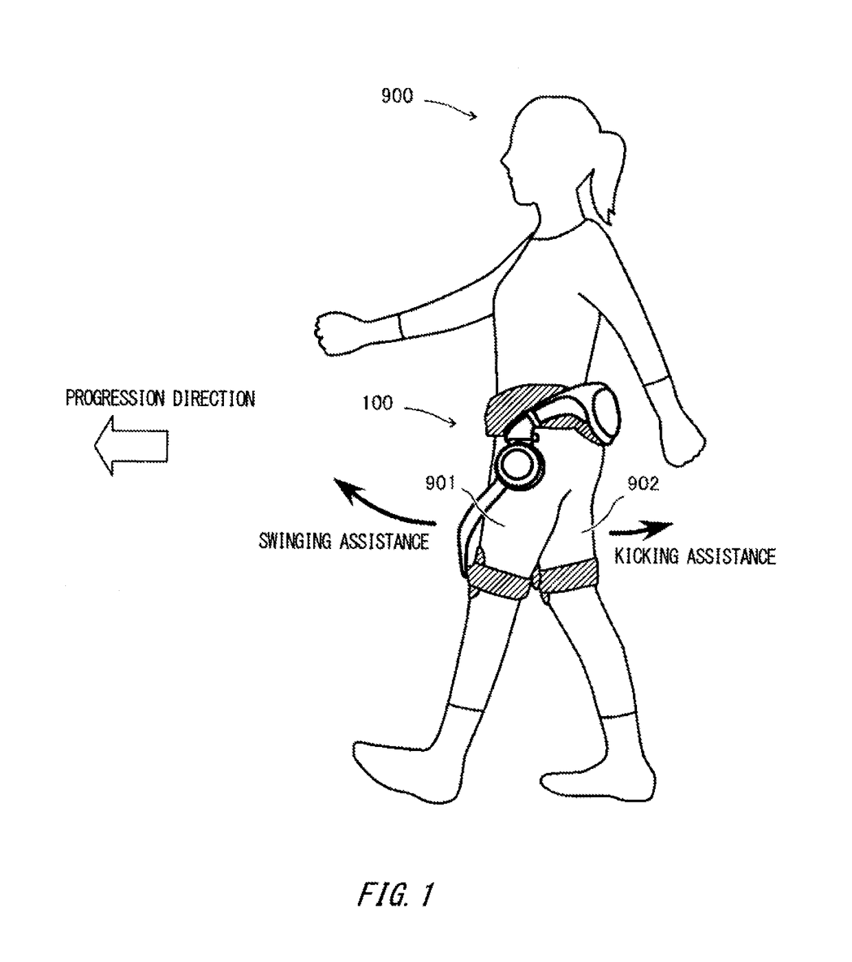
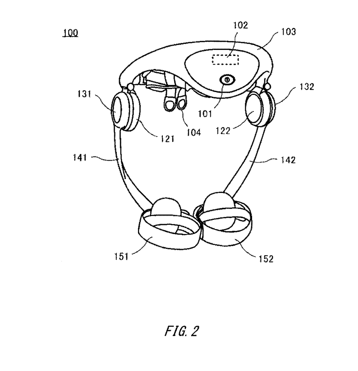
[0025]FIG. 1 is a view for describing a usage state of a step assist device 100 according to the present embodiment. A user 900 attaches and secures the step assist device 100 to the waist and leg regions. The step movement of a person generally includes alternating repetition of a movement of kicking out the pivot leg and a movement of swinging forward the other leg. For example, as shown in the drawing, when the right leg is the pivot leg and the left leg is swung, the step assist device 100 assists with the kicking by applying a backward auxiliary force to the right thigh 902 and assists with the swinging by applying a forward auxiliary force to the left thigh 901. On the other hand, when th...


PUM


Abstract

Provided is a step counter including a right angle sensor that outputs a right hip joint angle signal indicating a right hip joint angle of a user; a left angle sensor that outputs a left hip joint angle signal indicating a left hip joint angle of the user; a generating section that generates an angle difference signal indicating change over time of an angle difference between the right hip joint angle and the left hip joint angle, based on the right hip joint angle signal and the left hip joint angle signal; and a calculating section that calculates a step number of the user based on a difference signal generated from a difference between filtered signals resulting from the angle difference signal being applied to at least two different filters.

Description

[0001]The content of the following Japanese application is incorporated herein by reference:[0002]NO. 2014-126168 filed on Jun. 19, 2014.BACKGROUND[0003]1. Technical Field[0004]The present invention relates to a step counter, a step assist device and a step control program.[0005]2. Related Art[0006]A step counter is known that has an acceleration sensor mounted thereon, as shown in Patent Document 1, for example. A step assist device is known that can count the number of steps, as shown in Patent Document 2, for example.[0007]Patent Document 1: Japanese Patent Application Publication No. 2010-71779[0008]Patent Document 2: Japanese Patent Application Publication No. 2012-205826[0009]A step counter that uses an acceleration sensor or a step counter that detects contact between the sole of a foot and the ground can relatively easily count the number of steps for a healthy user, but if the user walks in an irregular manner, these step counters cannot accurately count the number of steps...

Claims


Application Information

Patent Timeline
Patent Type & Authority Patents(United States)
IPC IPC(8): A61H3/00A61H1/02
CPCA61H3/00A61H1/0244A61H2201/1215A61H2201/5069A61H2201/165A61H2201/1642A61H2201/163G01C22/006
Inventor ENDO, YOSUKE
Owner HONDA MOTOR CO LTD
Learn More