
Eye examination apparatus

a technology of eye examination and apparatus, which is applied in the field of eye examination apparatus, can solve the problems of inability to achieve the same degree of detail and natural color tones, the drawback is more pronounced in the case of infrared videos or photographs, and the need for high radiance illumination sources, etc., to achieve the effect of reducing light disturbance, maximizing light power, and being easy to produ

Active Publication Date: 2018-09-11
CENTVUE
View PDF13 Cites 0 Cited by
  • Summary
  • Abstract
  • Description
  • Claims
  • Application Information

AI Technical Summary

Benefits of technology

[0024]Within this aim, an object of the present invention is to provide an eye examination apparatus that allows maximization of the light power transmitted by the illuminator, especially in the peripheral regions of the retina examined where there is normally a lack of light.
[0025]A further object of the present invention is to provide an eye examination apparatus that is capable of acquiring images of the retina with a relatively wide field of view.
[0026]Another object of the present invention is to provide an eye examination apparatus that allows a reduction in light disturbances caused by reflections of the illumination light on its constituent parts (for example lenses or mechanical parts).
[0027]A further object of the present invention is to provide an eye examination apparatus capable of producing high contrast, infrared, color, red-free, fluorescence or autofluorescence videos and photographs of the retina.
[0028]A further object of the present invention is to provide an eye examination apparatus that is easy to produce on an industrial scale, at competitive costs.

Problems solved by technology

This drawback is more pronounced in the case of infrared videos or photographs.
An important drawback of confocal line scanning apparatus consists in that they require illumination sources with high radiance to obtain satisfactory illumination power to acquire the photos.
However, the color images thus obtained do not offer the same degree of detail and natural color tones as images obtainable with an examination apparatus that uses a light source capable of emitting white light.
However, due to insufficient radiance of the available white light sources, the solutions proposed to date have not led to mass-produced commercial products.
The photographic system described in this patent document does not provide practical solutions to improve, in a satisfactory manner, the transfer of power from the light source to the retina, so as to enable the use of low radiance white light sources, such as LED devices or the like.
This often causes the images acquired to be noisy, above all at the edges.
However, this solution increases the risk of movement of the eye during acquisition of the images, with the possible consequent presence of movement artefacts and blurring.
The solution proposed for the shape of the light source does not solve the problem of insufficient radiance of this latter.
A further drawback of prior art confocal line scanning apparatus consists in the fact that they do not typically allow photographs with sufficiently uniform distribution of brightness to be obtained, above all in the case of images corresponding to fields of view greater than around 30°.
This behavior makes it difficult to construct a collimating optics of the light source that supplies an output light beam having uniform power density.
This makes the distribution of brightness in the images of the retina even more non-uniform.
Any correction of an image acquired with non-uniform light distribution via software worsens the signal / noise ratio in the regions characterized by low brightness.
This reduces the quality of the images due to the increase in noise, making the images of little use for medical diagnosis.
If images with greater fields of view, for example of around 60°, are required, the fact of having light beams passing through different regions of some lenses of the apparatus causes different distortions in the aforesaid light beams, preventing the line of light projected on the retina to be optically conjugated, for the whole of its length, with the confocal diaphragm.
This causes a loss of brightness or the appearance of dark regions toward the outer edges of the images.

Method used


Image

  • Eye examination apparatus
  • Eye examination apparatus
  • Eye examination apparatus

Examples


Embodiment Construction

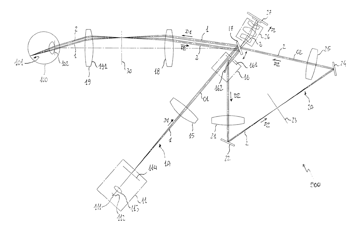
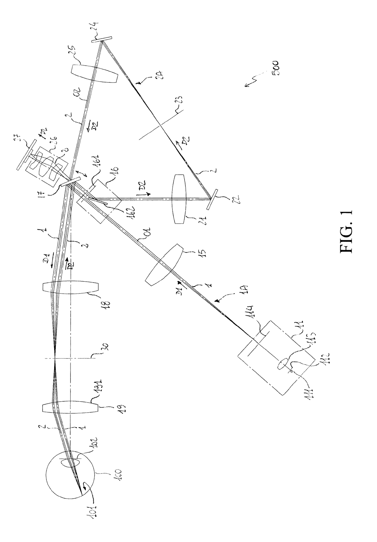
[0063]With reference to FIGS. 1-4, the present invention relates to an eye examination apparatus 500, in particular of confocal line scanning type. The apparatus 500 comprises a first illuminator 11 and an optical illumination path 1A having a first optical axis O1. Along the optical path 1A, a light beam 1 is projected in direction D1 by the illuminator 11 toward the retina 101 of the eye 100.

[0064]The apparatus 500 comprises acquisition means 27 adapted to receive light 2 reflected by the retina 101 and to acquire one or more images of the same retina.

[0065]The apparatus 500 comprises an optical imaging path 2A having a second optical axis O2. Along the optical path 2A, the light 2 reflected by the retina 101 travels in direction D2 until reaching the acquisition means 27.

[0066]The apparatus 500 comprises scanning means 17 adapted to move, along a scanning direction, the light beam 1 projected on the surface of the retina 101. Preferably, the scanning means 17 also have the functi...


PUM


Abstract

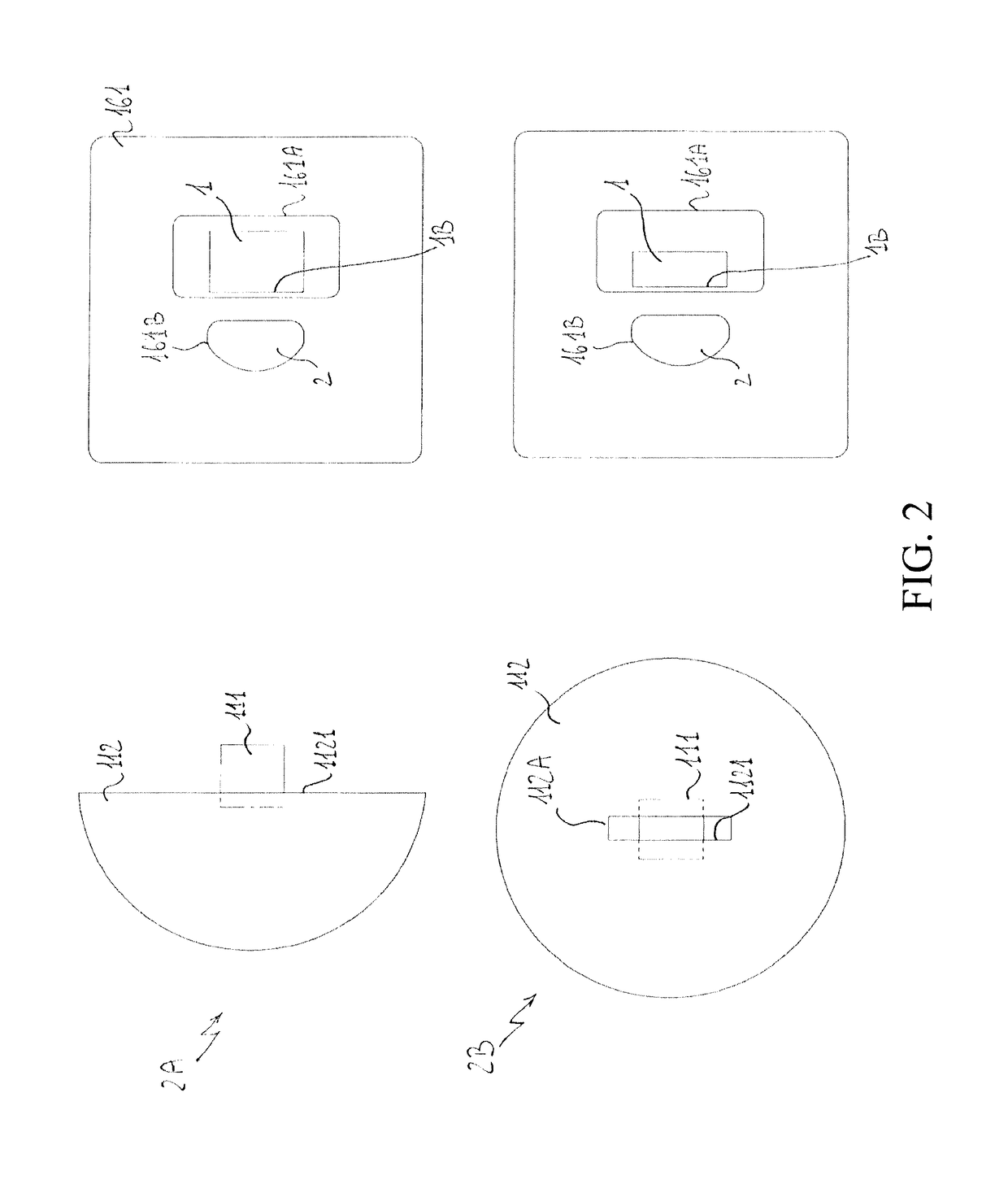
An eye examination apparatus comprises an illuminator adapted to project a light beam on an optical illumination path along a first optical axis to illuminate the retina of an eye, said illuminator comprising a light source and a projection diaphragm adapted to shape the light beam, during the operation of said examination apparatus said projection diaphragm being optically conjugated with the retina. Acquisition means receive light reflected by the retina and acquire images of the retina. Scanning means move the light beam projected on the surface of the retina along a scanning direction. Separation means of the beams separate the light projected by said illuminator from the light reflected by the retina. The projection diaphragm comprises a projection opening having an elongated shape and variable width, said projection opening comprising a portion having a width larger than the width of said projection opening at the first optical axis.

Description

BACKGROUND OF THE INVENTION[0001]The present invention relates to an eye examination apparatus.[0002]The apparatus according to the invention is preferably used in ophthalmology to acquire images of the retina. In general, however, it can be used to acquire images of any object.[0003]The use of apparatus for eye examination, commonly defined with the term “fundus cameras”, is widely known. In general, these apparatus illuminate the whole of the retina with a flash of white light and acquire the light reflected by the retina to produce color photographs of this latter.[0004]Usually, apparatus of this type, operating with the pupil not ciliated (non-mydriatic), are capable of photographing a relatively limited portion of the retina, corresponding to a maximum field of view of 45°, in conditions with pupil diameters of at least 4 mm. Some apparatus are also able to produce infrared videos and photographs.[0005]The images (color or infrared) that can be obtained by illuminating the whol...

Claims


Application Information

Patent Timeline
Patent Type & Authority Patents(United States)
IPC IPC(8): G02C5/00A61B3/10A61B3/15A61B3/00G02B5/00A61B3/12
CPCA61B3/12A61B3/0008G02B5/005A61B3/15A61B3/1025A61B3/154
Inventor PLAIAN, ANDREIMOGENTALE, IRENE
Owner CENTVUE
Learn More