Child motion apparatus

a technology of motion apparatus and pendulum, which is applied in the field of child motion apparatus, can solve the problems of limited range of movement paths, difficult to exert driving torque to overcome the gravitational force acting in the pendulum, and the drive system applied in most of the pendulum swing apparatus cannot allow truly adjustable swinging frequency

Active Publication Date: 2018-08-14
WONDERLAND SWITZERLAND AG
View PDF55 Cites 6 Cited by
  • Summary
  • Abstract
  • Description
  • Claims
  • Application Information

AI Technical Summary

Problems solved by technology

However, a few drawbacks may exist in the conventional swing apparatuses.
If a slower frequency of swinging motion is needed along a same motion path, it may be extremely difficult to exert a driving torque for overcoming the gravitational force acting in the pendulum motion.
Accordingly, the drive systems applied in most of the pendulum swing apparatuses cannot allow truly adjustable swinging frequency and have a limited range of movement paths.

Method used


Image

  • Child motion apparatus
  • Child motion apparatus
  • Child motion apparatus

Examples


Embodiment Construction

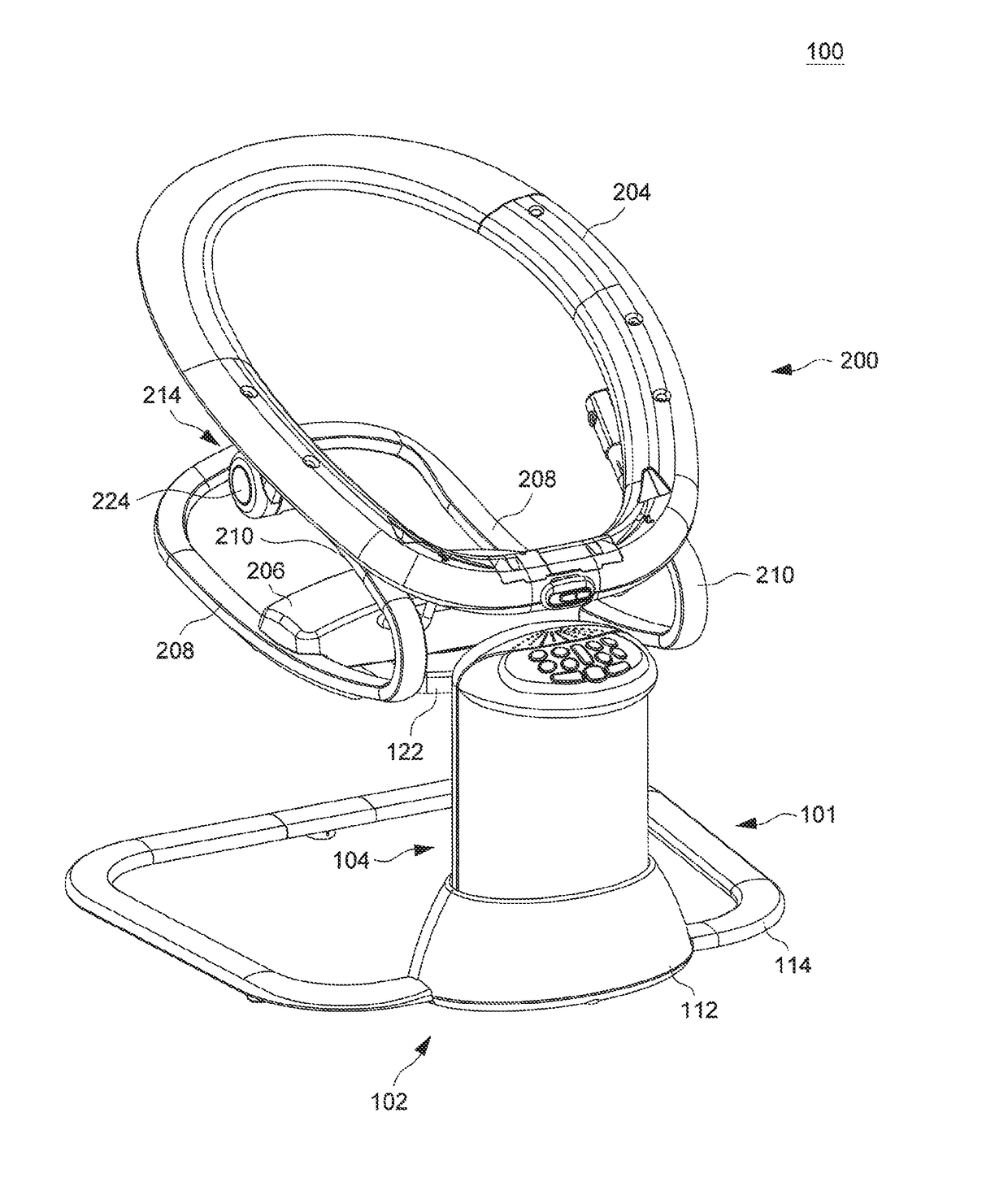
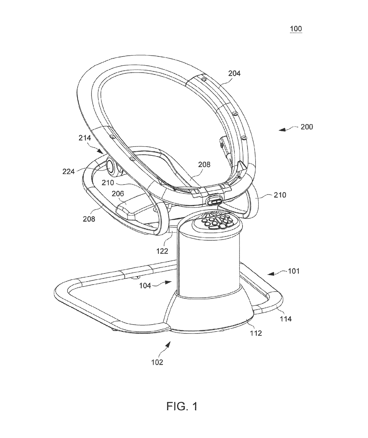
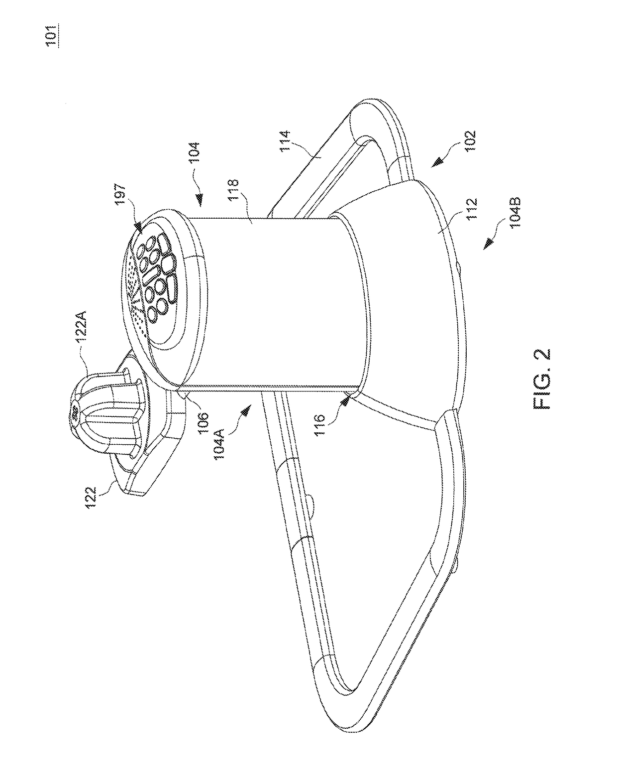
[0027]FIG. 1 is a perspective view illustrating an embodiment of a child motion apparatus 100, and FIG. 2 is a perspective view illustrating a portion of the child motion apparatus 100. Referring to FIGS. 1 and 2, the child motion apparatus 100 includes a motion drive unit 101 and a child seat 200. The motion drive unit 101 includes a base frame assembly 102, a column 104 and a support arm 106. The motion drive unit 101 can stand on a floor surface, and the child seat 200 adapted to receive a child can be detachably installed on the support arm 106. The motion drive unit 101 is electrically powered to drive movement of the support arm 106 and the child seat 200 installed thereon for soothing or entertaining a child received in the child seat 200.

[0028]In conjunction with FIGS. 1 and 2, FIG. 3 a a schematic view illustrating an inner construction of the motion drive unit 101, and FIG. 4 is a cross-sectional view of the motion drive unit 101. Referring to FIGS. 1-4, the base frame ass...


PUM


Abstract

A child motion apparatus includes a base frame assembly for providing standing support on a floor, a column assembled with the base frame assembly, a support arm extending generally horizontally relative to the column and having a first and a second end portion, a child seat connected with the second end portion of the support arm, a vertical actuating mechanism supported by the base frame assembly and operable to drive the column to slide upward and downward, and a horizontal actuating mechanism operable to drive the support arm to oscillate generally horizontally relative to the column. The first end portion of the support arm is assembled with the column and has a channel, and the horizontal actuating mechanism includes a driving part movable along a circular path and guided for sliding movement along the channel at the first end portion of the support arm.

Description

CROSS-REFERENCE TO RELATED APPLICATION(S)[0001]This application claims priority to U.S. Provisional Patent Application No. 62 / 166,418 filed on May 26, 2015, the disclosure of which is incorporated herein by reference.BACKGROUND[0002]1. Field of the Invention[0003]The present invention relates to child motion apparatuses.[0004]2. Description of the Related Art[0005]Swing apparatuses can be used by parents to help calming or entertaining a child. A child swing apparatus typically travels at a natural frequency in a pendulum motion. The drive system for the swing apparatus is generally located at the pivot point of the pendulum at a high location in the frame structure of the swing apparatus. While the conventional pendulum motion requires being driven when the system has the highest torque rendered by the gravity, the system can store the potential energy from one half cycle to another, requiring only a soft push or pull to maintain or increase the amplitude.[0006]However, a few drawb...

Claims


Application Information

Patent Timeline
Patent Type & Authority Patents(United States)
IPC IPC(8): A47D13/10
CPCA47D13/105A47D1/08A47D15/00A47D9/057A47D9/02A47D13/10
Inventor MOUNTZ, JONATHAN K.BELLOWS, WILLIAM B.
Owner WONDERLAND SWITZERLAND AG
Why Eureka
Try Eureka