
Mechanical seal lubrication system

a mechanical seal and lubrication system technology, applied in the direction of engine seals, non-positive displacement fluid engines, pump components, etc., can solve the problems of affecting the affecting the service life of the pump, and the temperature of the mechanical seal to rise, so as to prolong the service life and maintain the pump

Active Publication Date: 2018-07-31
VP SALES & COMPANY
View PDF12 Cites 0 Cited by
  • Summary
  • Abstract
  • Description
  • Claims
  • Application Information

AI Technical Summary

Benefits of technology

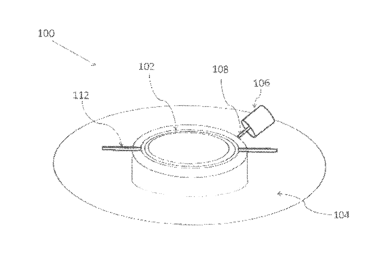
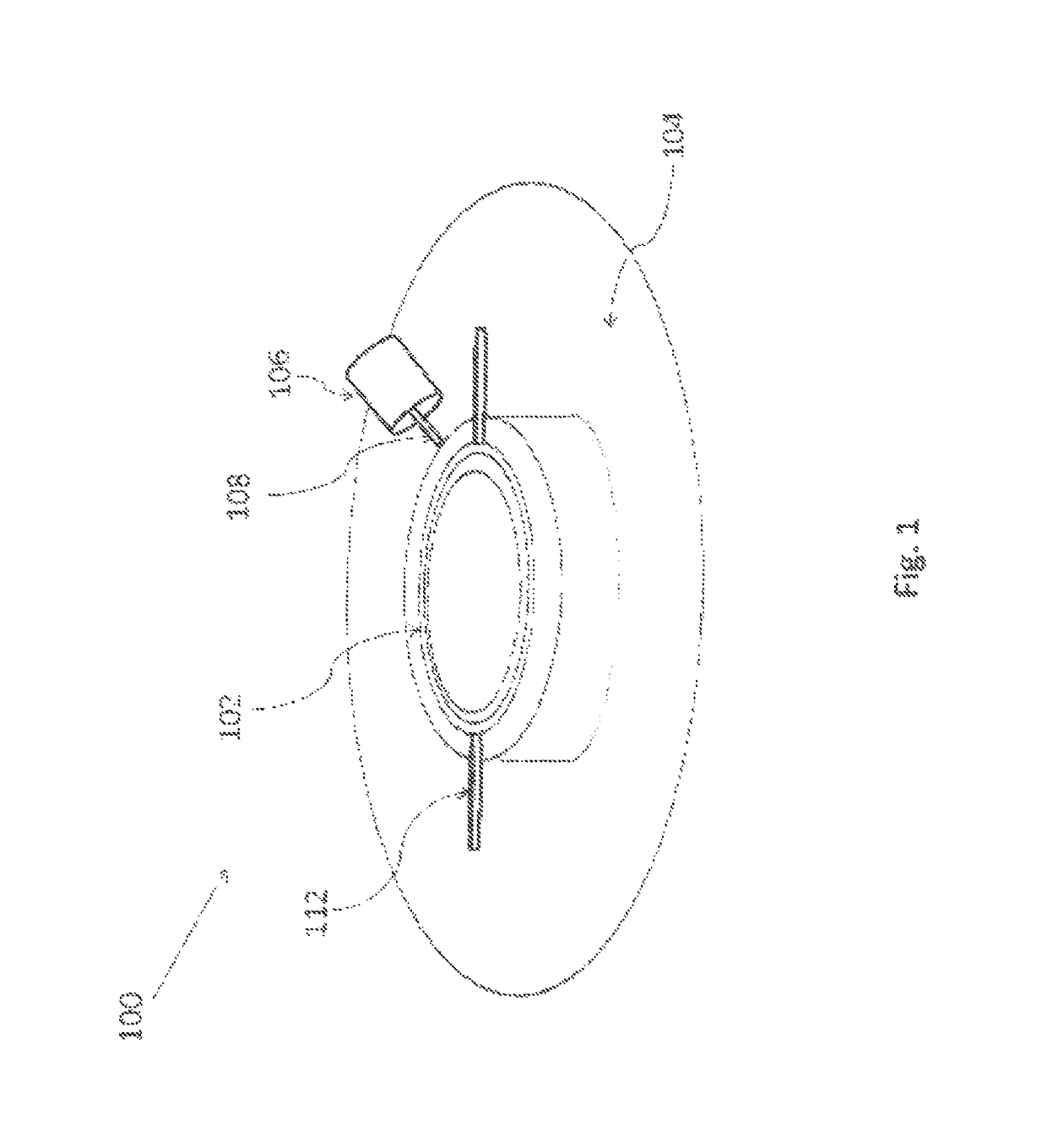
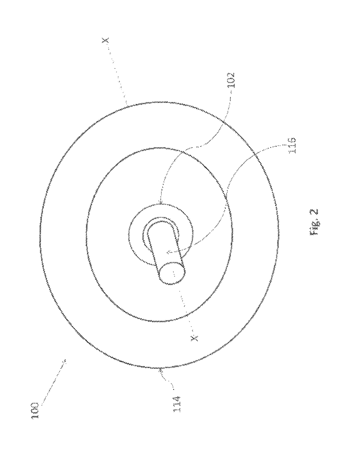
The patent describes a lubrication mechanism for centrifugal pumps that helps keep fluids flowing when the pump is unexpectedly shut off. This mechanism prevents damage to the mechanical seal and avoids rupturing caused by human or technical errors. The seal is placed along the shaft sleeve and is lubricated by an external oiler. The invention also includes a plurality of fins with grooves that help maintain the temperature of the seal and lubricant.

Problems solved by technology

In current industrial practice, the lubrication process of the centrifugal pump is operated without the use of control systems and thus there is no control on the fluctuating temperature of the lubricant.
In some cases when there is no fluid flowing through the pump due to human or technical errors, the pump has to be shut down as it may hamper the life of the pump.
In such conditions, absence of a coolant, such as oil field fluids, or oil as used ordinarily in pump applications, causes the temperature of the mechanical seal to rise.
This may cause the mechanical seal to crack; thereby damaging the mechanical seal.
If due to human or technical error, fluid stops flowing through the pump, the seal chamber might get heated up as it is placed on the inner side of the pump.
This increases the possibility of rupturing of the seal when the pump is in operation and there is no flow of fluid through the pump.
The above prior art systems and methods suffer from one of or more of disadvantages, including irregular lubricant supply to the pump and the mechanical seal, rupturing of the seal over short periods of time, human and technical errors, and so forth.

Method used


Image

  • Mechanical seal lubrication system
  • Mechanical seal lubrication system
  • Mechanical seal lubrication system

Examples


Embodiment Construction

[0028]As used in the specification and claims, the singular forms “a”, “an” and “the” include plural references unless the context clearly dictates otherwise. For example, the term “an article” may include a plurality of articles unless the context clearly dictates otherwise.

[0029]Those with ordinary skill in the art will appreciate that the elements in the Figures are illustrated for simplicity and clarity and are not necessarily drawn to scale. For example, the dimensions of some of the elements in the Figures may be exaggerated, relative to other elements, in order to improve the understanding of the present invention.

[0030]There may be additional components described in the foregoing application that are not depicted on one of the described drawings. In the event such a component is described, but not depicted in a drawing, the absence of such a drawing should not be considered as an omission of such design from the specification.

[0031]Before describing the present invention in ...


PUM


Abstract

Disclosed is a pump which comprises a mechanical seal lubricated by supplying lubricant from an external oiler. When there is no fluid flowing through the pump and the pump is in operation, the temperature of the mechanical seal rises. The lubricant from the oiler is supplied to the center of the mechanical seal through entry lines, and serves to maintain temperature within the pump and seal, while also avoiding failure of the seal. The lubricant keeps the mechanical seal cool and lubricated at all times.

Description

CROSS REFERENCE TO RELATED APPLICATION(S)[0001]This is a non-provisional patent application based on U.S. Provisional Patent Application Ser. No. 62 / 043,625 previously titled “Lubrication of Mechanical Seal”, filed on Aug. 29, 2014, the priority of which is hereby claimed and the disclosure of which is incorporated herein by reference in its entirety.BACKGROUND[0002]Field of the Invention[0003]The present invention generally relates to a method to prevent the rupturing of a mechanical seal used in centrifugal pumps. More particularly, the present invention relates to a lubrication mechanism for the mechanical seal.[0004]Description of the Related Art[0005]Centrifugal pumps are the most preferred hydrodynamic pumps used in domestic and industrial applications. The centrifugal pumps are provided with mechanical seals that are protective devices specially engineered to be used in the centrifugal pump. The primary function of a mechanical seal is to prevent liquid under pressure from le...

Claims


Application Information

Patent Timeline
Patent Type & Authority Patents(United States)
IPC IPC(8): F04D29/06F04D29/12F16J15/34
CPCF04D29/061F16J15/3404F04D29/126
Inventor MURRAY, PATRICK
Owner VP SALES & COMPANY
Learn More