
Electrical lighting system power control

a technology for lighting systems and power control, applied in high-level techniques, data switching networks, data switching details, etc., can solve problems such as non-standard poe schemes that have been proposed and implemented, and achieve the effect of reducing stand-by power consumption

Active Publication Date: 2018-07-24
SIGNIFY HLDG BV
View PDF44 Cites 0 Cited by
  • Summary
  • Abstract
  • Description
  • Claims
  • Application Information

AI Technical Summary

Benefits of technology

This solution minimizes standby power consumption by automatically switching off power to inactive luminaires, reducing overall network energy usage without requiring specialized controllers or commissioning, and can be implemented with minimal firmware updates to existing PoE switches.

Problems solved by technology

Also, non-standardized PoE schemes have been proposed and implemented hitherto.

Method used


Image

  • Electrical lighting system power control
  • Electrical lighting system power control
  • Electrical lighting system power control

Examples


Embodiment Construction

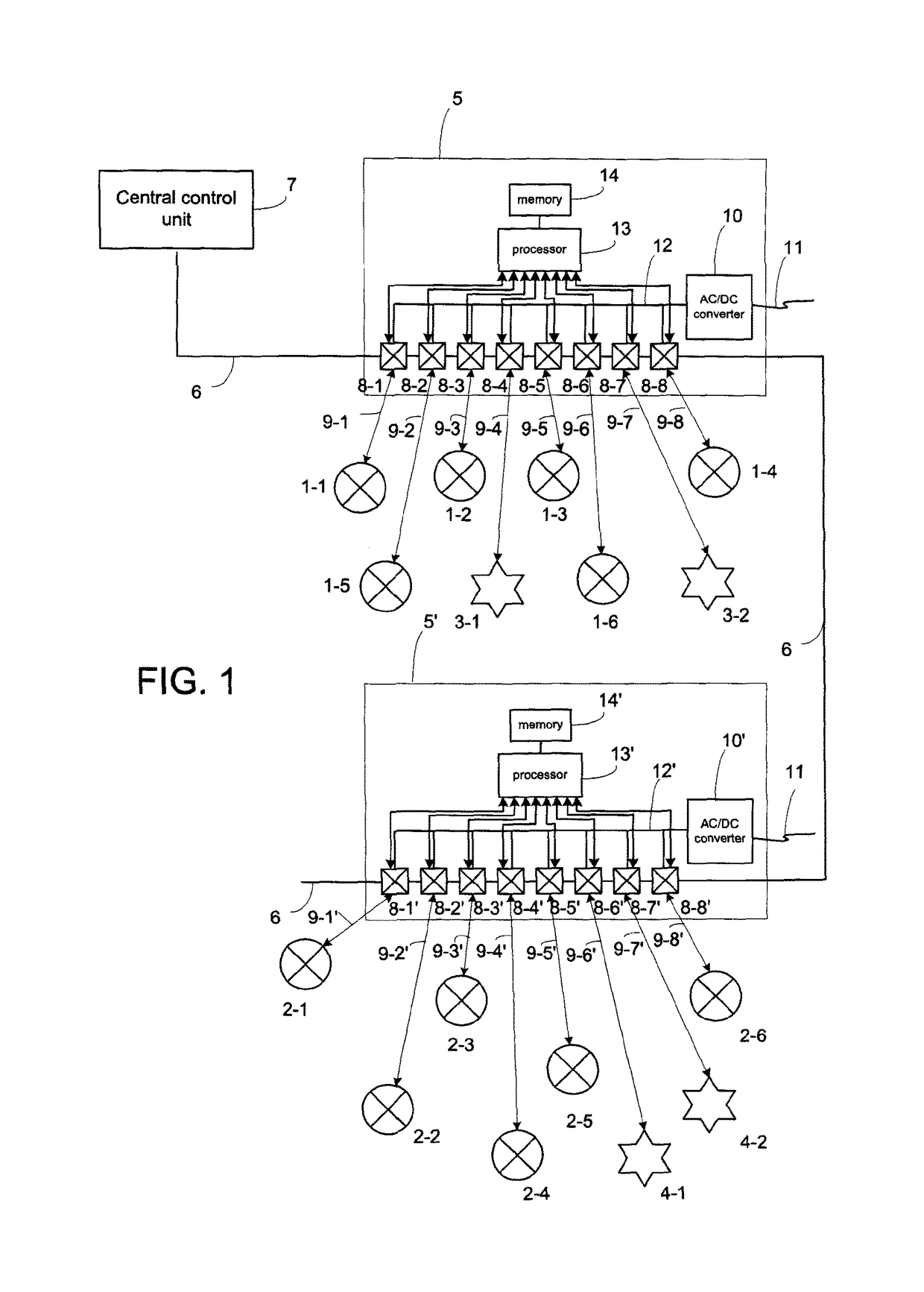
[0021]Referring to FIG. 1, a low voltage LED lighting network is illustrated schematically in which LED luminaires 1-1 . . . 1-6; 2-1 . . . 2-6 are connected in the network with sensors 3-1, 3-2; 4-1, 4-2.

[0022]The luminaires 1 and sensors 3 are coupled to a first PoE switch 5 and luminaires 2 along with sensors 4 are connected to a second PoE switch 6. The first and second PoE switches 5, 6 are connected in a digital network which allows IP data signals to be communicated between the switches and also a central lighting control unit 7 operable to transmit individually addressed IP data signals to the luminaires through the switches 5, 6. The communication between the central control unit 7 and the individual luminaires 1, 2 may be in any suitable digital format, for example the well known Digital Addressable Lighting Interface (DALI) format.

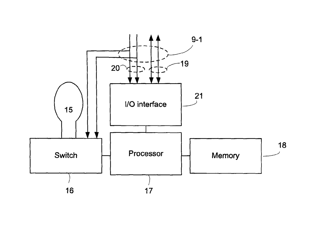
[0023]Considering the PoE switch 5 in more detail, a plurality of inputs / outputs that include switching elements 8-1 . . . 8-8 are connected by...


PUM


Abstract

A network switch (5) for example a PoE switch, is operable to control supply of electrical power to individual luminaires (1,2) in a lighting network. The luminaires receive both electrical power for operation and signals to switch on and off through a common cable connection (9) such as an Ethernet connection. When switched on, each luminaire sends a signal repeatedly towards the Po E switch until switched off and the switch (5) supplies power to the luminaire while successive signals are received within a period less than a predetermined shut off period (Δ). In this way, power to the luminaire can be disconnected to avoid consumption of standby power when not in use.

Description

CROSS-REFERENCE TO PRIOR APPLICATIONS[0001]This application is the U.S. National Phase application under 35 U.S.C. § 371 of International Application No. PCT / IB2012 / 055359, filed on Oct. 5, 2012, which claims the benefit of U.S. Provisional Application No. 61 / 543,861, filed on Oct. 6, 2011. These applications are hereby incorporated by reference herein.FIELD OF THE INVENTION[0002]This invention relates to electrical power control for lighting systems and has particular but not exclusive application to Power over the Ethernet (PoE) lighting systems.BACKGROUND OF THE INVENTION[0003]Some electrical lighting units such as LED luminaires can be driven at a lower voltage than a conventional mains AC supply, making low voltage.power distribution feasable in a lighting network.[0004]PoE has been developed for supplying low voltage power from a source such as a PoE switch, to a powered device such as a wi-fi access point or video camera, through the same Ethernet cable that carries signals t...

Claims


Application Information

Patent Timeline
Patent Type & Authority Patents(United States)
IPC IPC(8): H05B33/08H04L12/26H05B37/02H04L12/46H04L12/24H04L12/12H04L12/10H05B44/00
CPCH05B33/0842H04L12/10H04L12/12H04L12/4625H04L41/0833H05B37/0254H04L43/10Y10T307/74Y02D50/40Y02D50/42Y10T307/461H05B47/18Y02D30/50H05B45/37Y02B20/30H05B47/183H05B47/199H05B47/187H05B45/00
Inventor WANG, XIANGYU
Owner SIGNIFY HLDG BV
Learn More