Projection device

A technology of projection device and medium, applied in the direction of optical elements, optics, instruments, etc., can solve the problems of limited volume, problem of angle, and inability to reduce the thickness of rear-projection projection devices.

Inactive Publication Date: 2007-05-02
CHUNGHWA PICTURE TUBES LTD
View PDF0 Cites 0 Cited by
  • Summary
  • Abstract
  • Description
  • Claims
  • Application Information

AI Technical Summary

Problems solved by technology

However, when there is a problem with the angle at which the optical image 112 is transmitted to the display screen 120 or when the transmission path needs to be changed, the known rear-projection

Method used


Image

  • Projection device
  • Projection device
  • Projection device

Examples


Embodiment Construction

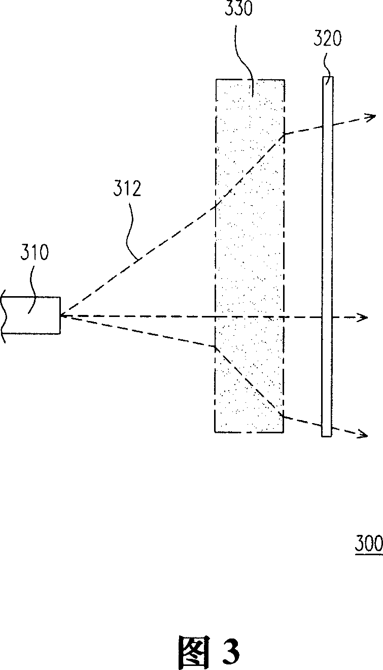
[0033] FIG. 3 is a schematic cross-sectional view of the structure of the projection device in the first embodiment of the present invention. Referring to FIG. 3 , the projection device 300 is mainly composed of a display screen 320 and an imaging system 310 . Wherein, the imaging system 310 is suitable for providing an optical image 312 , and the optical image 312 is transmitted to the display screen 320 through the optical transmission medium 330 with a refractive index not equal to 1. Here, the light transmission medium 330 may be a solid substance, a liquid substance, or a liquid crystal or the like.

[0034] It is worth mentioning that, in a preferred embodiment, the refractive index of the optical transmission medium 330 changes along the transmission path of the optical image 312, and this optical transmission medium 330 is, for example, made of two or more substances. composition. That is to say, the light transmission medium 330 may be solid material, liquid materia...


PUM


Abstract

A projection device is featured as providing optical image by imaging system, transmitting said optical image to display screen by light transmission media with refractivity being not equal to one, enabling to change transmission path of optical image by controlling refractivity of light transmission media so as to make said projection device be thin and small.

Description

technical field [0001] The present invention relates to a projection device, and in particular to a projection device capable of reducing the overall volume by adjusting the light refraction path through a medium or a reflective element. Background technique [0002] The rapid progress of the multimedia society is mostly due to the rapid progress of semiconductor components and displays. As far as the display is concerned, since the direct-view display still has many limitations on large-scale display, the rear-projection projector and Rear projection TV has gradually become the mainstream trend. [0003] FIG. 1 and FIG. 2 are schematic cross-sectional views of two conventional rear-projection projection devices, respectively. Please refer to FIG. 1, the known rear projection device 100 directly transmits the optical image 112 to the display screen 120 through the imaging system 110, and the rear projection device 200 in FIG. 2 also provides the optical image 112 through t...

Claims


Application Information

Patent Timeline
IPC IPC(8): G02B27/18G02B1/00G02B17/08G02B26/08
Inventor 陈志隆张燃宏郑伊凯周明德
Owner CHUNGHWA PICTURE TUBES LTD
Why Eureka
Try Eureka