Solar inverter and photovoltaic installation comprising several solar inverters

A technology for optoelectronic equipment and inverters, which is used in photovoltaic power generation, irreversible DC power input conversion to AC power output, and optical radiation generators.

Inactive Publication Date: 2007-04-25
SIEMENS AG
View PDF1 Cites 18 Cited by
  • Summary
  • Abstract
  • Description
  • Claims
  • Application Information

AI Technical Summary

Problems solved by technology

[0008] The disadvantage of the first described solution is that a separate monitoring device has to be installed, which represents an additional investment for the operator of the optoelectronic installation
[0009] The disadvantage of the second solution is that an additional PC with special software applications is necessary in order to be able to carry out routine checks of the equipment

Method used


Image

  • Solar inverter and photovoltaic installation comprising several solar inverters

Examples


Embodiment Construction

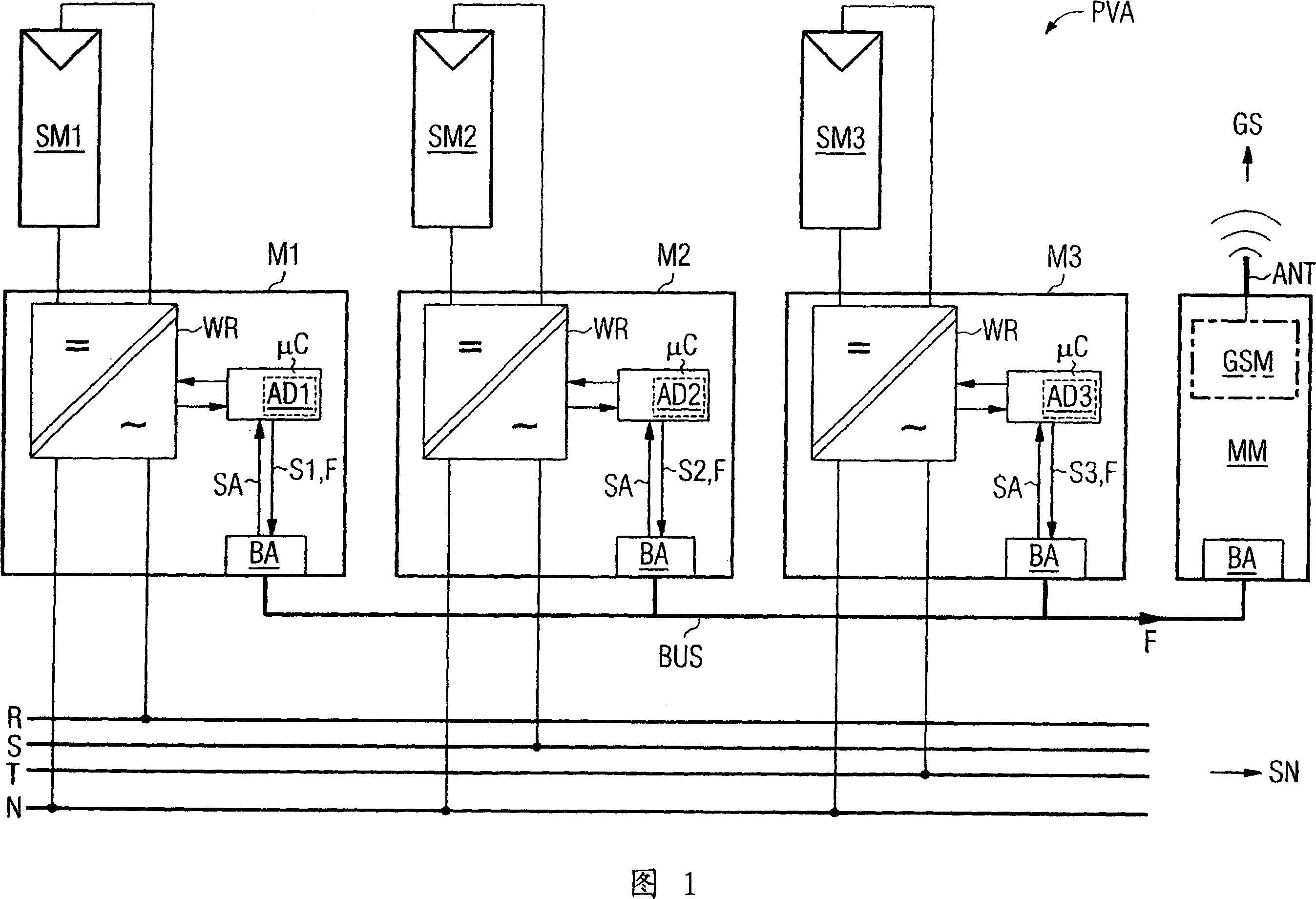
[0032] FIG. 1 shows a photovoltaic system PVA according to the invention, which schematically has three photovoltaic generators SM1-SM3. For clarity, their internal structures are not further shown. Here, the photovoltaic generators SM1-SM3 feed the respective solar inverters M1-M3. In the example of FIG. 1, each solar inverter M1-M3 has an inverter module WR whose input is connected to a photovoltaic generator SM1-SM3. Here, the solar direct current is converted into a single-phase alternating voltage. As already realized in this example, for safety reasons these voltages are potential free with respect to the levels of the photoelectric generators SM1-SM3.

[0033]In the example of FIG. 1 , three solar inverters M1 - M3 each feed a phase line R, S, T of the grid SN in order to achieve an approximately uniform power distribution in the grid SN. Such a grid SN is in particular a public three-phase 50 Hz / 400 V voltage grid. N denotes the common neutral of all three feeding ...


PUM


Abstract

In one aspect, a solar inverter which can be connected to at least one photovoltaic generator at the input end and to a power system at the output end is provided. The solar inverter includes an inverter module, an electronic control unit at least for diagnosing an inverter module, and a bus interface for technically connecting the electronic control unit to a communication bus. The electronic control unit cyclically outputs a piece of status information of the solar inverter on the communication bus, and outputs an error message on the communication bus, cyclically reads status information of other solar inverters that are connected to the communication bus, and outputs an error message on the communication bus in case at least one expected additional piece of status information fails to be output. Whereby, the need for a separate monitoring unit is eliminated.

Description

technical field [0001] The invention relates to a solar inverter which can be connected at an input to at least one photovoltaic generator and at an output to a grid, in particular a utility grid; and comprises at least one inverter module, at least for diagnostics The electronic control unit of the inverter module, and the bus connector for connecting the electronic control unit with the communication bus in data technology. [0002] The invention relates to a photovoltaic system which feeds a grid, in particular a utility grid, with a plurality of solar inverters, to which at least one photovoltaic generator can be connected. Background technique [0003] Photoelectric equipment is used to feed current into the grid, such as a single-phase 50Hz / 230V voltage grid or a three-phase 50Hz / 400V voltage grid. For this purpose, the photovoltaic system can have one or more photovoltaic generators, wherein the photovoltaic generator can consist of one or more solar modules, which i...

Claims


Application Information

Patent Timeline
Patent Type & Authority Applications(China)
IPC IPC(8): H02M7/48H02J3/38H02J13/00H02M7/44H02N6/00
CPCY02E40/72H02J3/383Y04S10/123H02J13/0062Y02E10/566H02J3/382H02M7/493Y02E10/563H02J2300/24H02J3/381H02J13/00016Y02E10/56Y02E40/70Y04S40/124Y02E60/00H02M7/521H02M7/48H02J7/35
Inventor 罗兰·伯格
Owner SIEMENS AG
Why Eureka
Try Eureka