Baby rack
A baby and seat technology, applied in the field of baby chairs, can solve problems such as the limitation of the length of the rocker in the up and down direction and the extension of the main body cycle of the seat.
- Summary
- Abstract
- Description
- Claims
- Application Information
AI Technical Summary
Problems solved by technology
Method used
Image

Examples
no. 1 Embodiment approach
[0046] 1 to 7 are diagrams showing a first embodiment of the baby chair of the present invention.
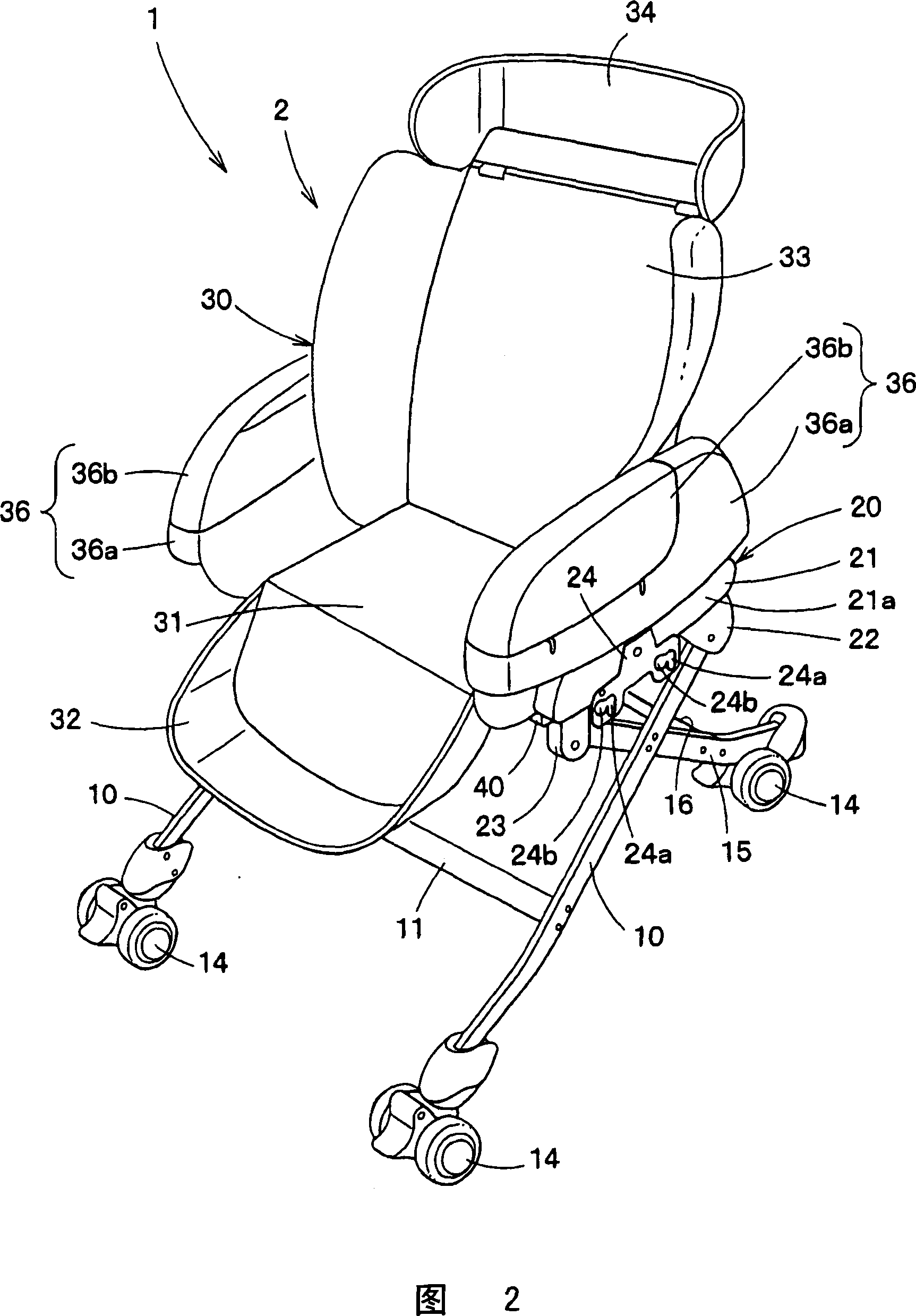
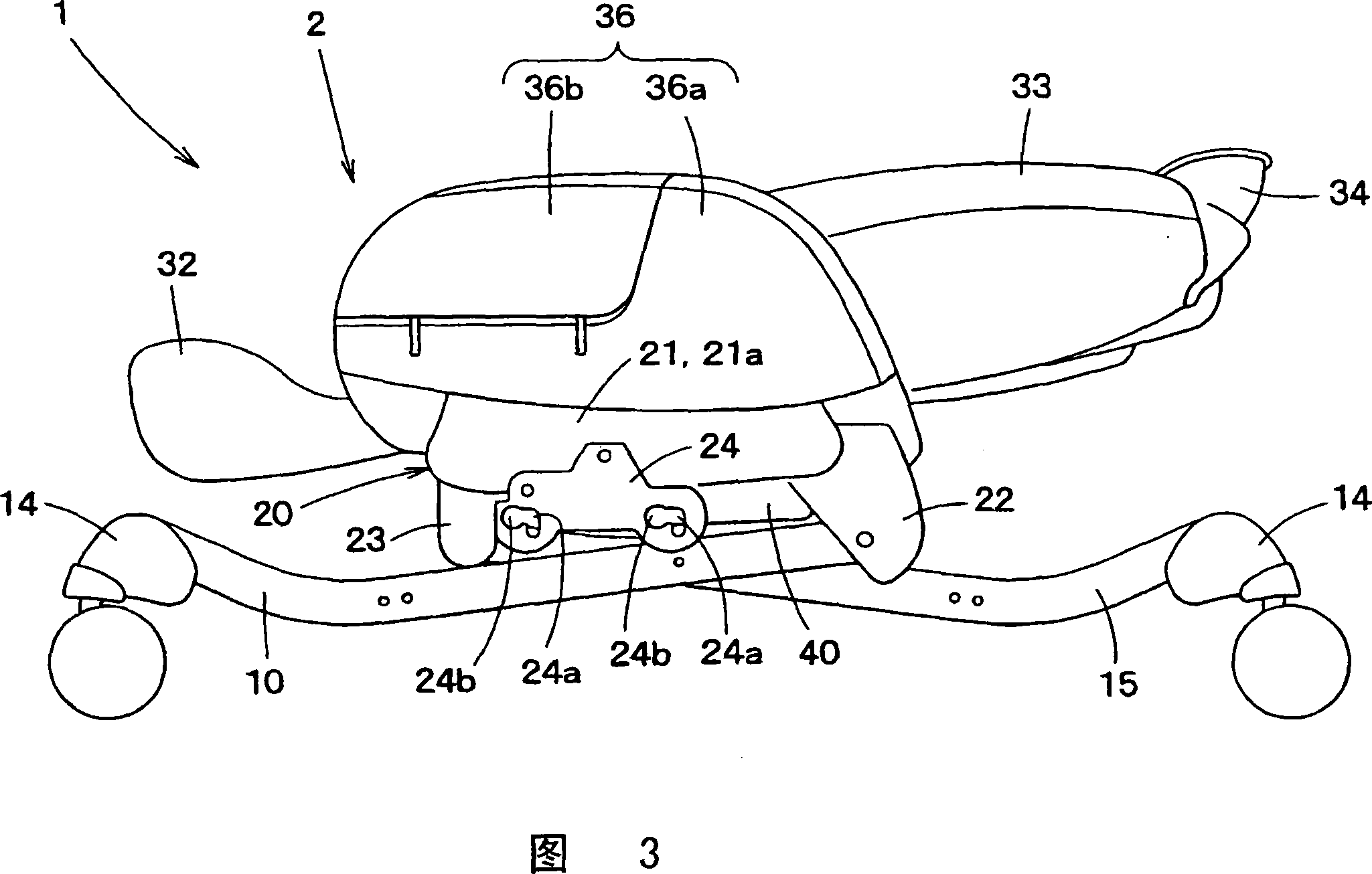
[0047] 1 is a perspective view of the baby chair, FIG. 2 is a perspective view of the baby chair with the storage box removed, and FIG. 3 is a side view of the baby chair with the storage box removed.
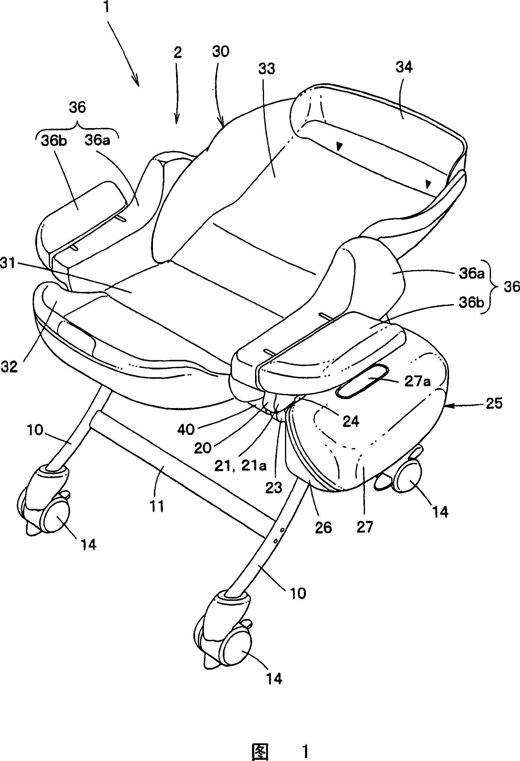
[0048] As shown in FIGS. 1 to 3 , the baby chair 1 includes: a pair of left and right front legs 10 , 10 and rear legs 15 , 15 with casters 14 at the lower end, connected to each front leg 10 , 10 and rear leg 15 . A pair of side plates 20, 20 on the left and right of the upper end of 15, a swing mechanism 40 disposed between the side plates 20, 20, and a seat main body 30 arranged on the top of the swing mechanism 40 are freely detachably mounted on the side plate 20. storage box 25.
[0049] Such a baby chair 1 can be used as a chair for infants as shown in FIG. 2 , and can also be used as a bed for infants as shown in FIG. 1 .
[0050]
[0051]First, the overall structure ...
no. 2 Embodiment approach
[0103] Next, a second embodiment of the present invention will be described with reference to FIGS. 8 and 9 .
[0104] The second embodiment shown in FIGS. 8 and 9 differs only in the swing mechanism, and is substantially the same as the first embodiment shown in FIGS. 1 to 7 in other respects.
[0105] Therefore, detailed descriptions of parts other than the swing mechanism are omitted, and in FIGS. 8 and 9 , even for the swing mechanism, the same parts as those of the first embodiment shown in FIGS. 1 to 7 are given the same symbols and detailed descriptions are omitted. .
[0106] In addition, FIG. 8 is a side view of the swing mechanism 70 , and FIG. 9 is a front view of the swing mechanism 70 .
[0107] As shown in FIGS. 8 and 9 , the rocking mechanism 70 has a fixed portion 41 , a fan-shaped roller 71 disposed on the fixed portion 41 and constituting a substantially fan-shaped column with at least an arc portion 71 a in cross section, and the arc portion 71 a faces the ...
no. 3 Embodiment approach
[0126] Next, a third embodiment of the present invention will be described with reference to FIGS. 10 to 12 .
[0127] The third embodiment shown in FIGS. 10 to 12 is different only in the rocking mechanism, and is substantially the same as the first embodiment shown in FIGS. 1 to 7 and the second embodiment shown in FIGS. 8 and 9 .
[0128] Therefore, the detailed description of parts other than the swing mechanism is omitted, and in FIGS. Detailed description is omitted.
[0129] In addition, FIG. 10 is a plan view of the swing mechanism 76, FIG. 11 is a front view of the swing mechanism 76, and FIG. 12 is a cross-sectional view taken along line 12-12 of FIG.
[0130] As shown in FIGS. 10 to 12 , the swing mechanism 76 includes a fixed portion 41 having a side wall 41 b extending in the front-rear direction of the seat body 30 , and a first swing body that hangs freely from the side wall 41 b of the fixed portion 41 . 77. The swing frame 79 supported on the first swing bod...
PUM
 Abstract
Description
Claims
Application Information
 - Generate Ideas
- Intellectual Property
- Life Sciences
- Materials
- Tech Scout
- Unparalleled Data Quality
- Higher Quality Content
- 60% Fewer Hallucinations
Browse by: Latest US Patents, China's latest patents, Technical Efficacy Thesaurus, Application Domain, Technology Topic, Popular Technical Reports.
© 2025 PatSnap. All rights reserved.Legal|Privacy policy|Modern Slavery Act Transparency Statement|Sitemap|About US| Contact US: help@patsnap.com