Condensating apparatus and its complete drying equipment and dehumidifying equipment

A drying equipment and water condensation technology, which is applied in the field of drying equipment and dehumidification equipment, can solve problems such as flawed structural design, failure to condense, poor water removal effect, etc., to achieve a wide range of applications and ensure nutritional value.

Inactive Publication Date: 2007-03-28
JINZHAN COOP
View PDF0 Cites 3 Cited by
  • Summary
  • Abstract
  • Description
  • Claims
  • Application Information

AI Technical Summary

Problems solved by technology

[0002] Please refer to China Taiwan Announcement No. 90117283 "Pneumatic Air Dehydration Device" invention patent (hereinafter referred to as the conventional case), which is a kind of high-pressure air that can condense the moisture in the air in the container However, the excluded technology has flaws in its structural design, and fails to effectively condense the moisture in the air; please refer to the examples shown in Figures 3 to 8 of the prior art, and its examples There is a common disadvantage, that is, when the air enters the cylinder groove 110 from the air inlet 122, it enters into the first air chamber 112 and the water collection chamber 114 at the same time, because the first air chamber 112 and the water collection chamber 114 are connected, so that The pressure of the incoming air drops sharply, and the water molecules contained in the air entering the first air chamber 112 cannot effectively collide and condense on the wall surface, making the effect of water removal poor, and needs to be improved

Method used


Image

  • Condensating apparatus and its complete drying equipment and dehumidifying equipment
  • Condensating apparatus and its complete drying equipment and dehumidifying equipment
  • Condensating apparatus and its complete drying equipment and dehumidifying equipment

Examples


Embodiment Construction

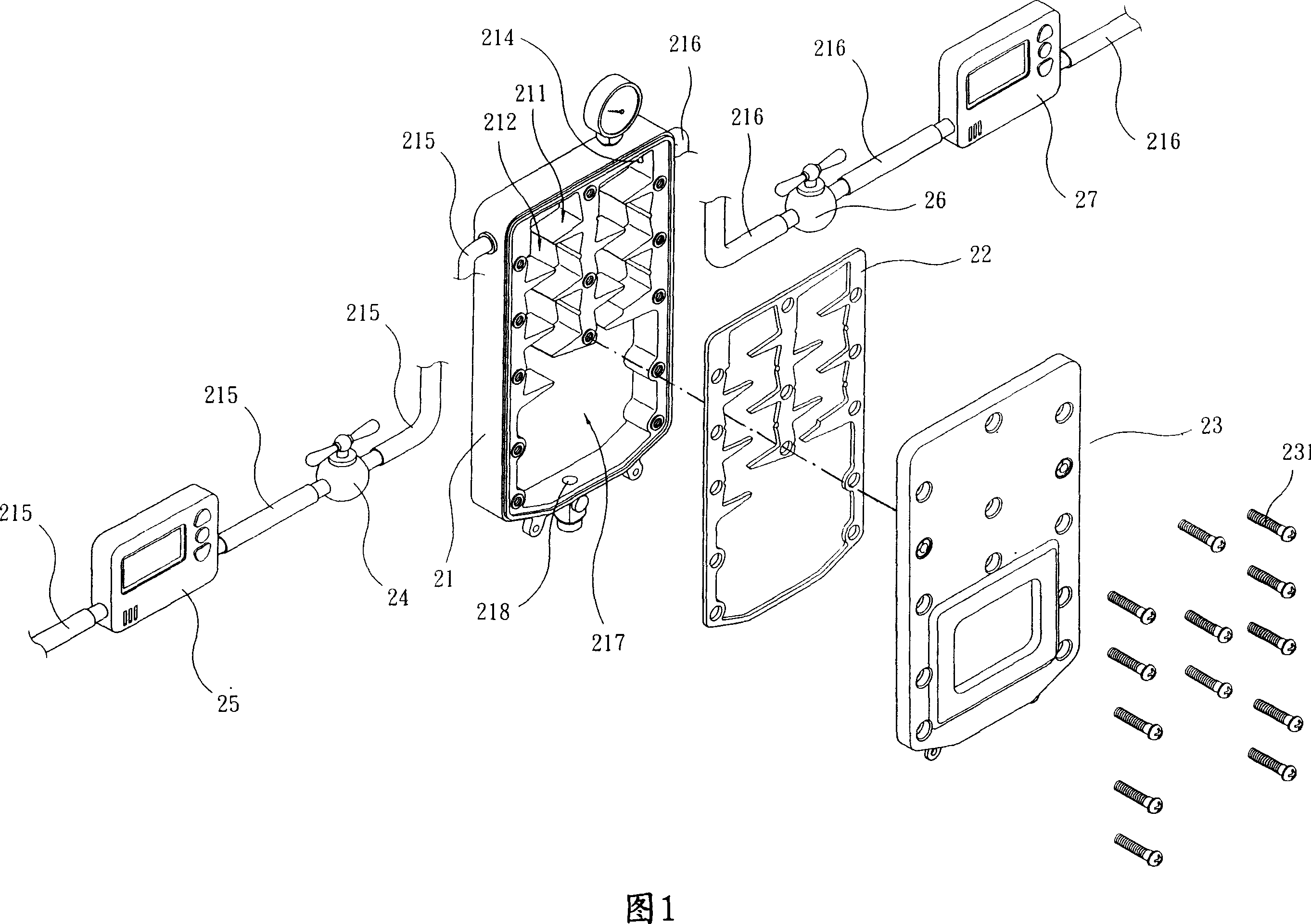
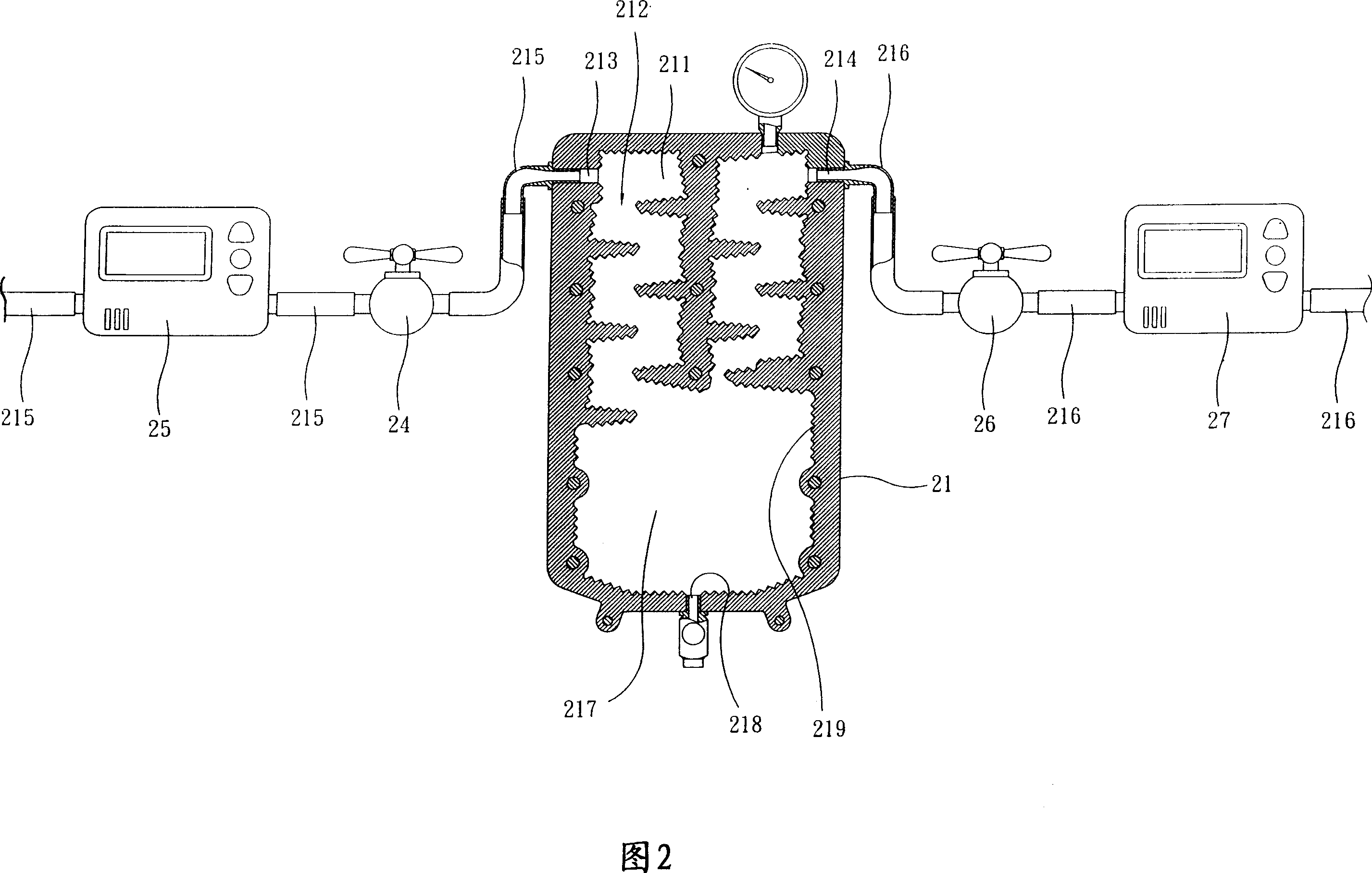
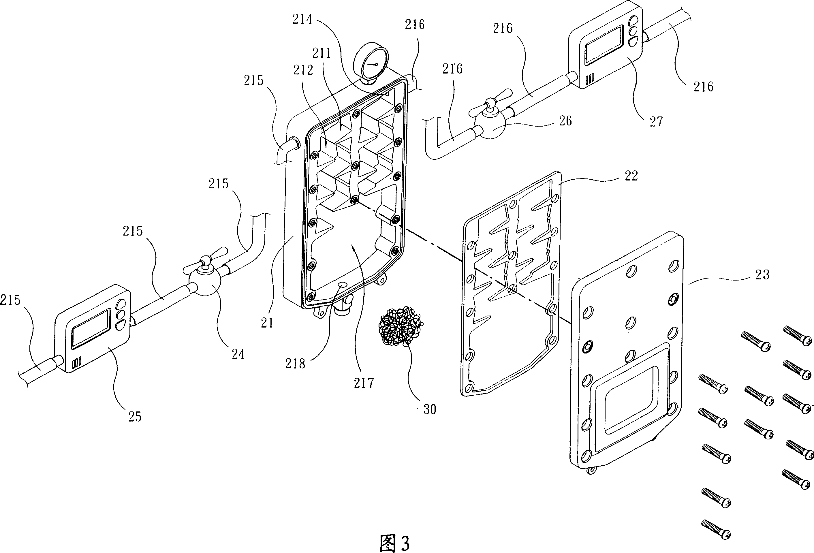
[0049] Please refer to Fig. 1 , which is the first embodiment of the present invention. The condensation device of this embodiment is to integrally form several concave collision chambers 211 on a body 21, and one end surface of the body 21 is covered with a cover. 23 is covered and sealed, and a leak-proof gasket 22 is provided between the cover 23 and the end surface of the body 21. The body 21 is provided with an air inlet 213 (cooperating with FIG. 2), an air outlet 214, and a drain 218. The air inlet 213 It communicates with the first collision chamber, and the air outlet 214 communicates with the last collision chamber, and the air inlet 213 and the air outlet 214 are located above the body 21, and the drain 218 is located below the body 21; A through hole 212 is provided between the collision chambers 211 so that the adjacent collision chambers can be communicated; in addition, the arrangement positions of the collision chambers 211 do not have a certain position, and it...


PUM


Abstract

The present invention relates to a water-condensing equipment and its matched drying equipment and dehumidification equipment. It is characterized by that it includes several collision chambers, said several collision chambers can be combined into one body or series-connected together, all the collision chambers are mutually communicated, the interior wall of every collision chamber has convexo-concave rough surface, so that when the high-pressure air containing water can be fed into the collision chamber interior so as to produce collision, the water molecule can be condensed and the humidity of said air also can be reduced.

Description

technical field [0001] The invention relates to a condensation device and drying equipment and dehumidification equipment matched with it. Background technique [0002] Please refer to China Taiwan Announcement No. 90117283 "Pneumatic Air Dehydration Device" invention patent (hereinafter referred to as the conventional case), which is a kind of high-pressure air that can condense the moisture in the air in the container However, the excluded technology has flaws in its structural design, and fails to effectively condense the moisture in the air; please refer to the examples shown in Figures 3 to 8 of the prior art, and its examples There is a common disadvantage, that is, when the air enters the cylinder groove 110 from the air inlet 122, it enters into the first air chamber 112 and the water collection chamber 114 at the same time, because the first air chamber 112 and the water collection chamber 114 are connected, so that The pressure of the incoming air drops sharply, a...

Claims


Application Information

Patent Timeline
IPC IPC(8): B01D53/26F24F3/14
Inventor 蔡瑞云郭志仁吴蓉桢
Owner JINZHAN COOP
Why Eureka
Try Eureka