
Torsion beam type suspension

A technology of torsion beam suspension and torsion beam, which is applied in the direction of suspension, elastic suspension, interconnection system, etc.

Active Publication Date: 2010-09-22
MAZDA MOTOR CORP
View PDF1 Cites 0 Cited by
  • Summary
  • Abstract
  • Description
  • Claims
  • Application Information

AI Technical Summary

Problems solved by technology

Therefore, as shown in the above-mentioned Patent Document 1, when the spring seat is connected to the torsion beam and the suspension trailing arm, the spring seat will apply an excessive torsional force to the torsion beam by the force from the coil spring and the shock absorber, thereby Causes problems in the performance and strength of the torsion beam suspension

Method used


Image

  • Torsion beam type suspension
  • Torsion beam type suspension
  • Torsion beam type suspension

Examples


Embodiment Construction

[0038] Hereinafter, embodiments of the present invention will be described with reference to the drawings.

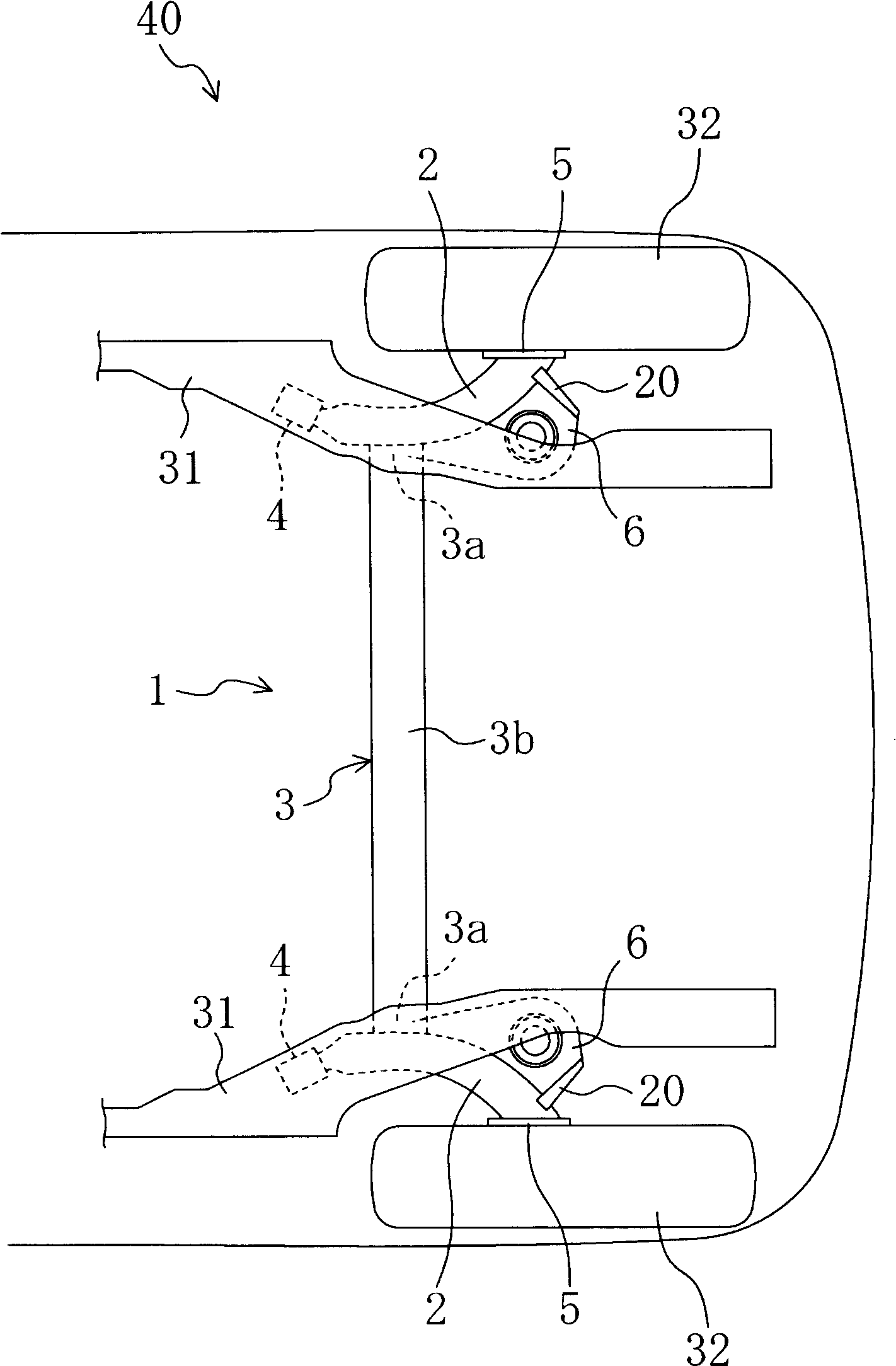
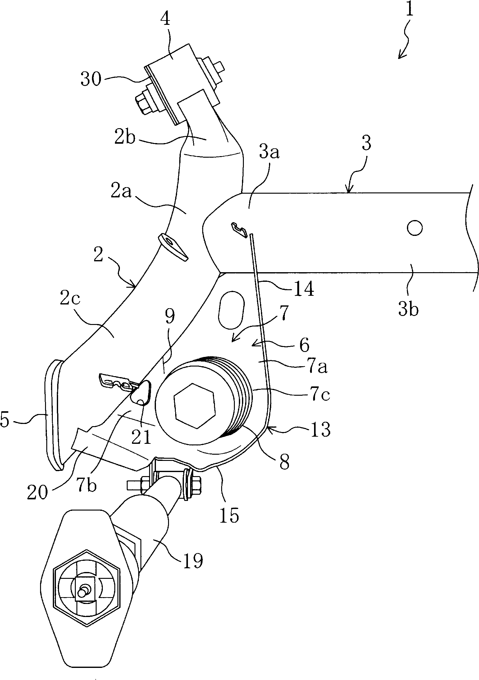
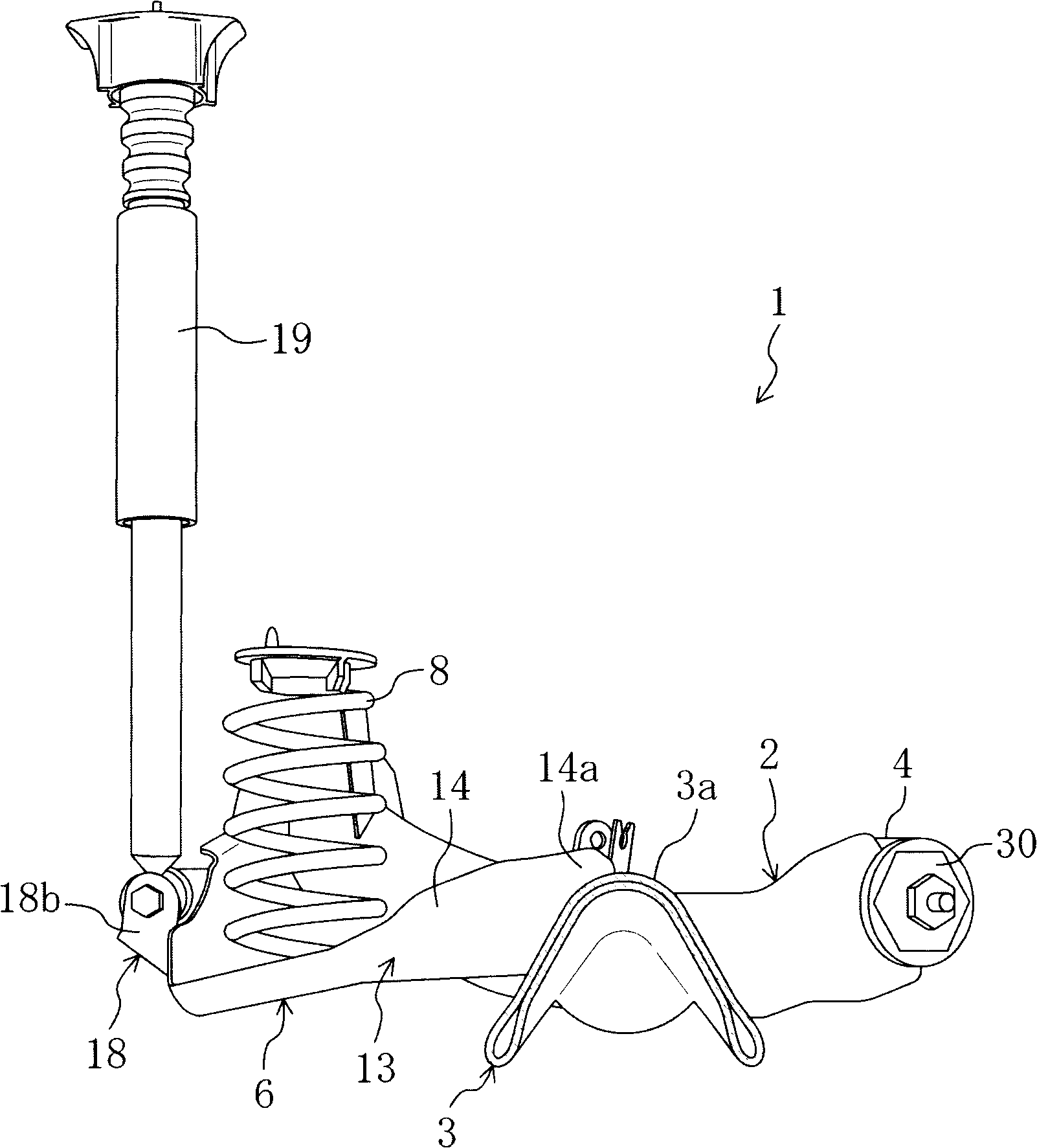
[0039] figure 1 It is a top view showing a vehicle body rear portion 40 having the torsion beam suspension 1 according to the embodiment of the present invention. Figure 2 to Figure 4 These are enlarged views of the left side portion of the torsion beam suspension 1 viewed from above the vehicle, from the inside in the width direction of the vehicle, and from the rear of the vehicle, respectively. The torsion beam suspension 1 includes a pair of left and right suspension trailing arms 2 extending in the vehicle front-rear direction, and a torsion beam 3 extending in the vehicle width direction. A pair of suspension trailing arms 2 are connected to both ends of the torsion beam 3 by welding each longitudinal end 3 a of the torsion beam 3 to the front-rear central portion 2 a of the suspension trailing arm 2 .

[0040]The above-mentioned torsion beam 3 forms a closed ...


PUM


Abstract

Provided is a torsion beam type suspension comprising a pair of suspension trailing arms (a left one and a right one) extending along fore-and-aft direction of a vehicle with a front end rotatablely supporting the vehicle body and a back end free-rotatablely supporting the back wheels; a torsion beam extending along breadth direction of the vehicle with ends in longitudinal direction connecting with center parts in fore-and-aft direction of the suspension trailing arms; a cant part formed by ends in longitudinal direction of the torsion beam and a back side part of the suspension trailing arms, and fixed on the torsion beam and the suspension trailing arms, and provided, at the rear part of which, with a spring seat of the mounting seat for helix springs; a buffer mounting seat for mounting the buffer arranged at the back of the spring seat. The spring seat has a bottom wall part which supports the helix springs and is connected with the trailing arms but not the torsion beam; a flange part bends upwardly from the bottom wall part and is connected with the torsion beam and the trailing arm; and a reinforcing part extending rearward is provided in the vicinity of the buffer mounting seat of the flange part. This invention can securely support the load from a damper and prevent a spring seat from excessively transmitting torsion to a torsion beam, even when the spring seat having a damper fitting seat is connected with the torsion beam and a trailing arm.

Description

technical field [0001] The present invention relates to a torsion beam type suspension having a torsion beam extending in the width direction of a vehicle and having each end in the length direction connected to a front-rear central portion of a trailing arm of the suspension. Background technique [0002] The known torsion beam suspension in the past includes a pair of left and right suspension trailing arms extending along the front and rear direction of the vehicle, the front end of which may be supported on the vehicle body for swinging, and the rear end of which is freely rotatable to support the rear wheel; along the vehicle width direction A torsion beam that extends, each end in the longitudinal direction of which is connected to the central portion in the front-rear direction of the above-mentioned suspension trailing arm; provided at the corner formed by each end in the longitudinal direction of the torsion beam and the rear side portion of the above-mentioned susp...

Claims


Application Information

Patent Timeline
Patent Type & Authority Patents(China)
IPC IPC(8): B60G11/20
CPCB60G2206/012B60G2200/21B60G2202/136B60G2206/20B60G21/051B60G21/052
Inventor 日下勇树原田一夫
Owner MAZDA MOTOR CORP
Learn More