
Method for reducing co-channel interference in sector interval

A co-channel interference and inter-sector technology, which is applied in network planning, electrical components, transmission systems, etc., can solve problems such as weak correlation, submersion, and terminal B cannot receive correctly, so as to eliminate mutual interference and avoid dropouts. The effect of words

Inactive Publication Date: 2007-02-14
CHINA ACAD OF TELECOMM TECH
View PDF2 Cites 4 Cited by
  • Summary
  • Abstract
  • Description
  • Claims
  • Application Information

AI Technical Summary

Problems solved by technology

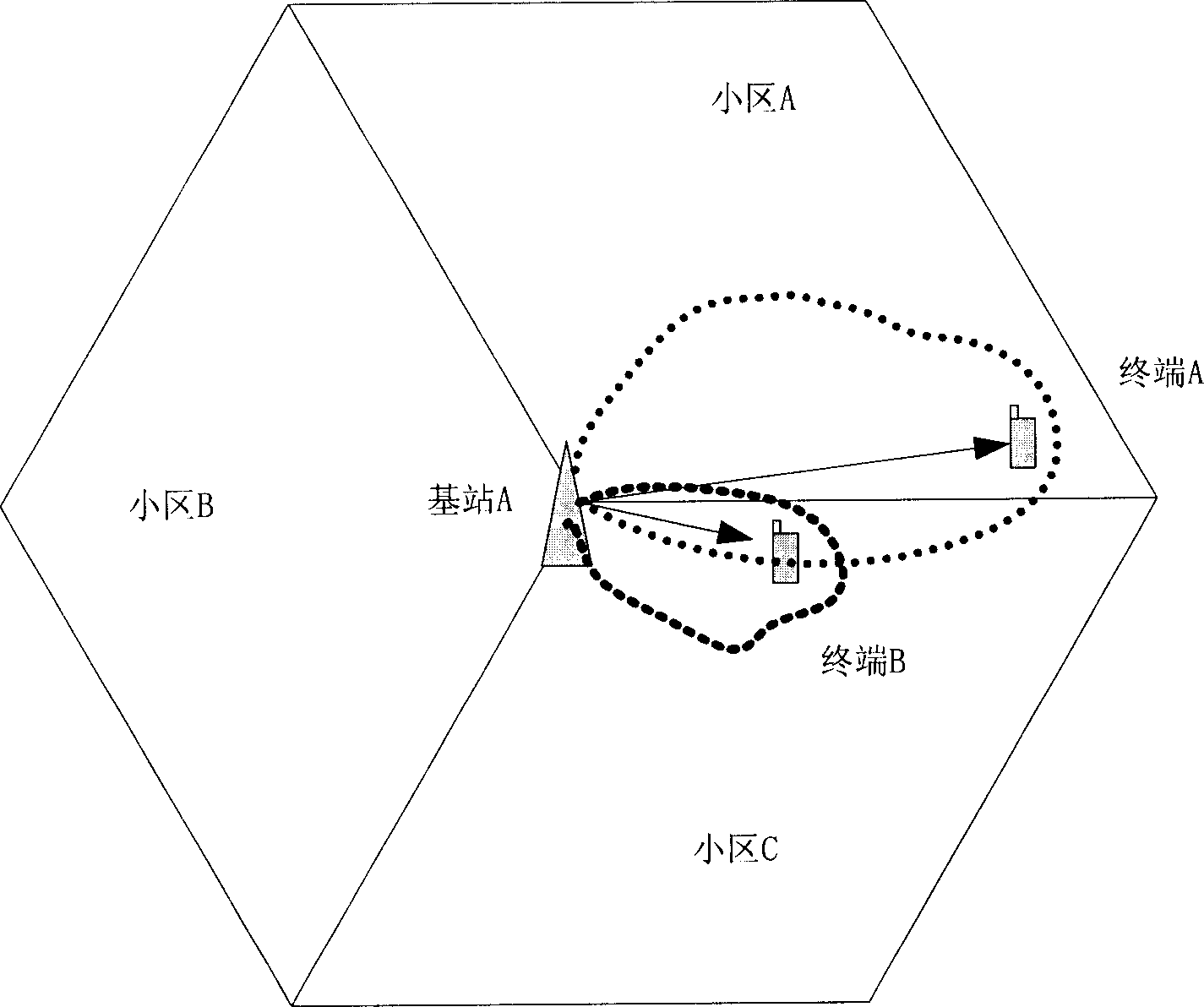
In this scenario, since both terminal A and terminal B are relatively close to the edge area between cell A and cell C, the shaped beams of their respective smart antennas are relatively wide. When terminal A and terminal B have the same working time slot, the Strong overlapping interference between beams is formed, and the joint detection technology generally used only for eliminating interference between users in a cell cannot eliminate such inter-cell interference
The existing scrambling code planning technology can't solve the problem. We have analyzed above. Due to the effect of scrambling codes, the actual spreading codes of users between cells in the TD-SCDMA system can no longer guarantee complete orthogonality. When the spreading codes of terminal A and terminal B have a certain correlation, the signals between the two terminals will form a certain degree of interference
Especially when terminal A is far away from base station A and terminal B is relatively close to base station A, in the downlink direction, since the base station needs to transmit stronger power to terminal A to overcome the influence of transmission path loss, at this time terminal B receives The signal transmitted by the base station to terminal A also has relatively strong power. At this time, the useful signal transmitted to terminal B may be submerged in the signal transmitted to terminal A, even if the correlation between the two user spreading codes is not very strong It will also bring a lot of interference and cause terminal B to fail to receive the signal correctly

Method used


Image

  • Method for reducing co-channel interference in sector interval
  • Method for reducing co-channel interference in sector interval
  • Method for reducing co-channel interference in sector interval

Examples


Embodiment Construction

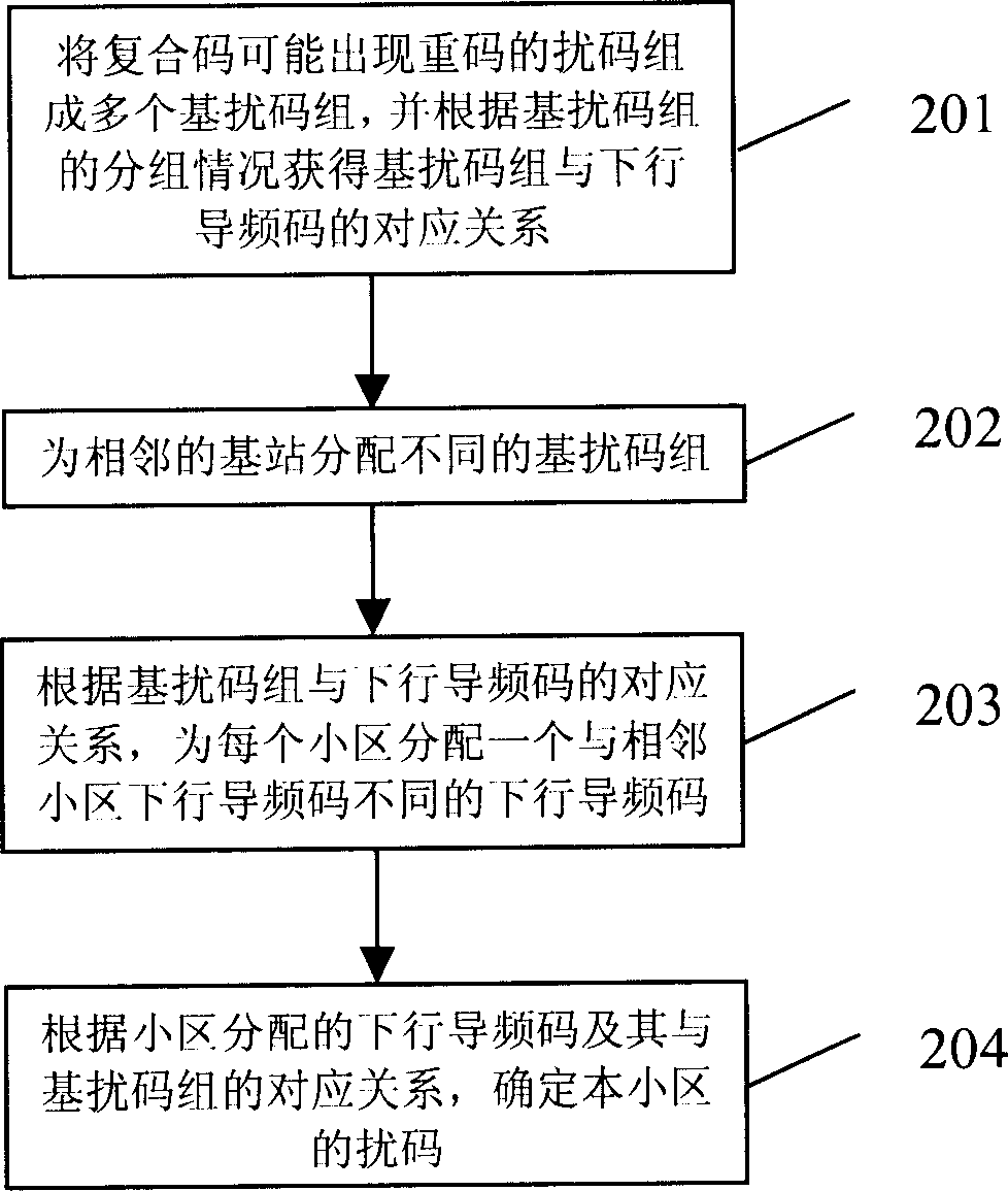
[0061] The core of the present invention is that according to the characteristics of the scrambling codes of the TD-SCDMA system, the scrambling codes of which the compound codes may have repeated codes are respectively formed into the basic scrambling code groups. When assigning scrambling codes to each cell (including omnidirectional cells and sectorized cells), first assign different base scrambling code groups to adjacent base stations to ensure that the scrambling codes of each cell under the same base station belong to the same base scrambling codes; then assign downlink pilot codes to each cell according to the corresponding relationship between the base scrambling code group and the downlink pilot code, and then further determine the scrambling codes of each cell to ensure that the scrambling codes allocated between cells belonging to different base stations belong to different base scrambling code group. When the terminal initially accesses the system and during the m...


PUM


Abstract

The invention discloses a method for decreasing the frequency interference of sectors, including: compositing the scrambling codes of the repeated codes which are likely to happen in the complex codes to form a number of base-scrambling code groups, and obtaining the corresponding relationships between the base-scrambling code groups and the downlink pilot-codes according to the splitting situation of the groups; distributing different base scrambling codes to the adjacent base stations; distributing a downlink pilot-code for each area which is different from the ones of the adjacent area according to the corresponding relationships between the base-scrambling code groups and the downlink pilot-codes; determining the scrambling code of this area based on the corresponding relationships between the distributed downlink pilot-codes and the base-scrambling code groups.

Description

technical field [0001] The invention relates to the technical field of mobile communication, in particular to a method for reducing co-frequency interference between sectors. Background technique [0002] An important means to improve system capacity and spectrum efficiency in a cellular mobile communication system is to adopt a sectorized cell structure. Sectorization of cells can not only improve the spectrum utilization rate of the system, but also reduce the demand for base station sites. Therefore, it has become one of the main economic networking methods. In the TD-SCDMA (Time Division-Synchronous Code Division Multiple Access) system, although key technologies such as smart antennas and joint detection have been adopted to greatly increase the system capacity, supporting sectorized cells is still an indispensable improvement. means of system capacity. [0003] In the sectorized cellular mobile communication system, the non-ideality of the antenna radiation pattern w...

Claims


Application Information

Patent Timeline
Patent Type & Authority Applications(China)
IPC IPC(8): H04Q7/36H04B1/707H04W16/14
Inventor 毕海
Owner CHINA ACAD OF TELECOMM TECH
Learn More