
Actuator

A technology of actuators and bases, applied in instruments, piezoelectric devices/electrostrictive devices, piezoelectric/electrostrictive/magnetostrictive devices, etc., can solve the problem of increased cost, huge amount of data, and difficult displacement Correction control in the direction of recovery, etc., to achieve high reliability

Inactive Publication Date: 2007-01-31
PANASONIC CORP
View PDF1 Cites 3 Cited by
  • Summary
  • Abstract
  • Description
  • Claims
  • Application Information

AI Technical Summary

Problems solved by technology

In particular, since the driving force is generated only in the suction direction during electrostatic driving, it is difficult to correct the displacement caused by the disturbance to the return direction.
In addition, when the characteristics of the microactuator are scattered, the amount of data for correcting the displacement caused by the disturbance becomes huge.
In particular, in a device (micromirror array, etc.) equipped with a plurality of microactuators, if the disturbance is large, the amount of data for correcting the displacement caused by the disturbance becomes huge
This becomes a cause of a significant cost increase and a reduction in the driving speed of the microactuator

Method used


Image

  • Actuator
  • Actuator
  • Actuator

Examples


Embodiment Construction

[0053] Hereinafter, embodiments of an actuator and a device including the actuator according to the present invention will be described with reference to the drawings.

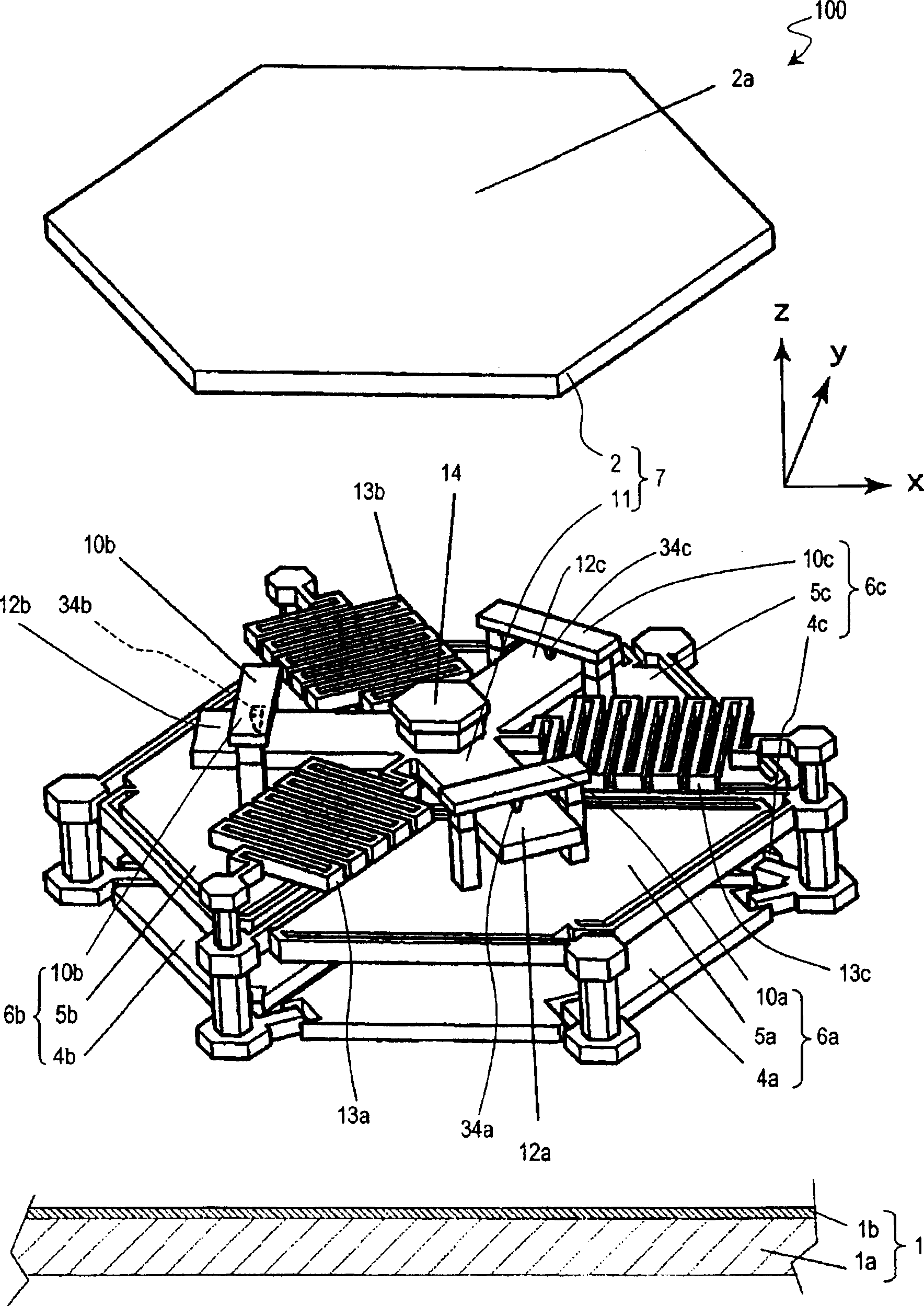
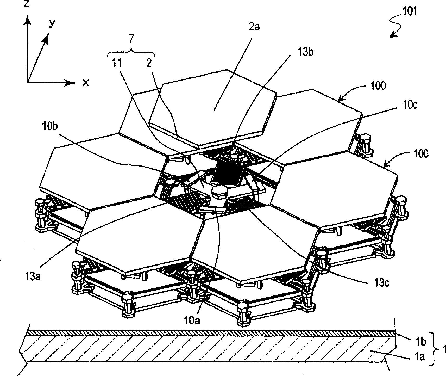
[0054] First, refer to figure 1 . figure 1 It is a schematic exploded perspective view showing the actuator 100 of this embodiment. The actuator 100 is manufactured using micromachining technology using semiconductor manufacturing processes and MEMS technology.

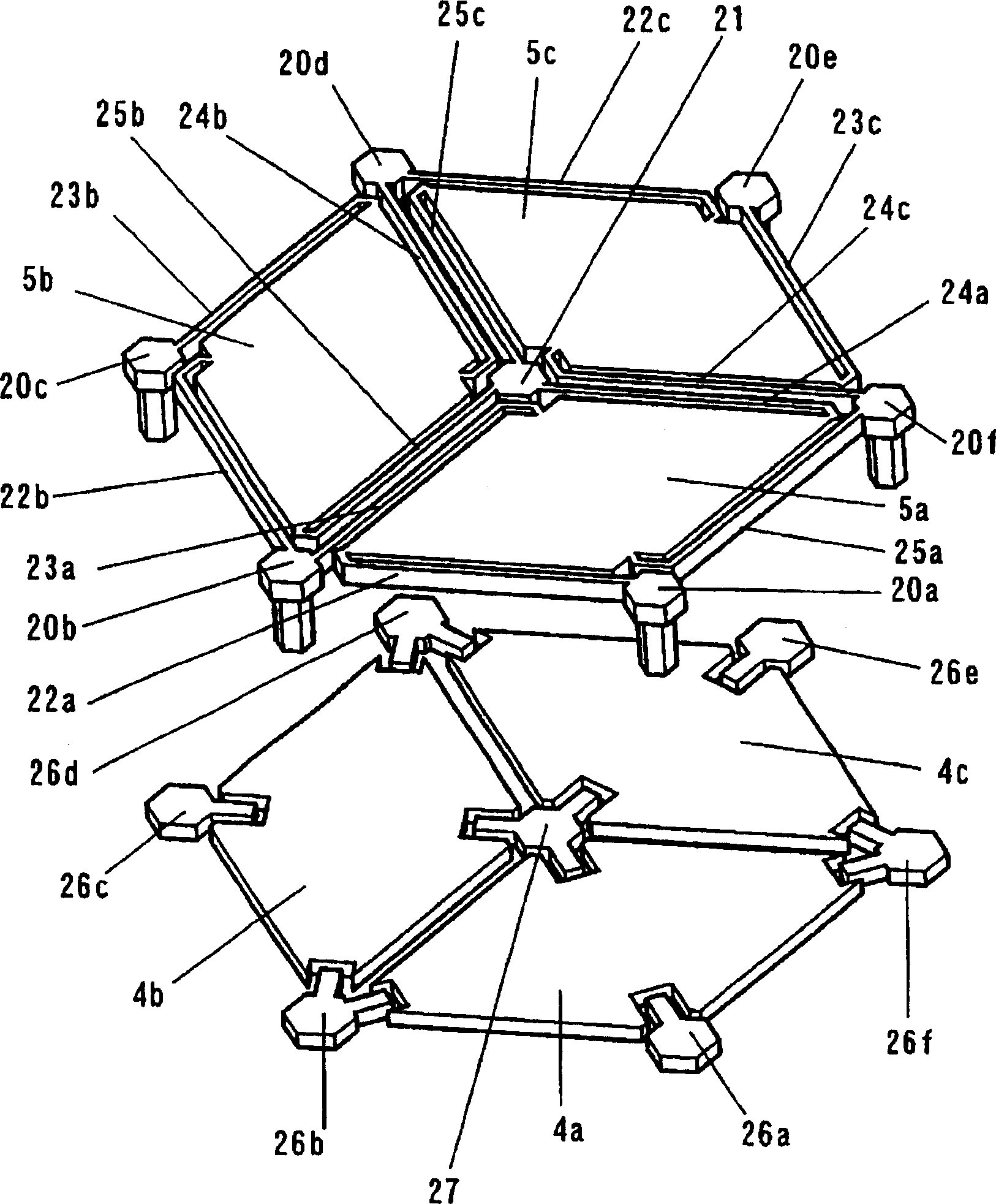
[0055] The actuator 100 includes: a base 1; a movable part 7 capable of displacing relative to the base 1; and 13c; and a plurality of drive portions 6a, 6b, and 6c for displacing the movable portion 7 relative to the base 1 .

[0056] The susceptor 1 includes a silicon member 1a, and a silicon nitride-based insulating layer 1b formed on the silicon member 1a. A driving circuit (not shown in the figure) is formed on the silicon member 1a. The drive units 6a to 6c are provided on the insulating layer 1b. Via holes (not shown in the figure) are ...


PUM


Abstract

An actuator has a base (1), a movable section (7) capable of being displaced relative to the base (1), elastic supporting sections (13a-13c) for supporting the movable section (7) so that it can be displaced relative to the base (1), and drive sections (6a-6c) for displacing the movable section (7) relative to the base (1). The drive sections (6a-6c) have drive force transmitting sections (10a-10c) coming into contact with the movable section when transmitting a drive force to the movable section (7).

Description

technical field [0001] The invention relates to an actuator capable of tilting and vertical displacement. The actuator of the present invention is used, for example, as a micromirror device having a light reflecting surface on a movable part. Background technique [0002] Using MEMS (Micro Electro Mechanical System) technology to manufacture various micro-actuators, and expect micro-actuators to be applied to various fields such as optics, high-frequency wave circuits, and bioengineering technology. For example, in the field of adaptive optics, micromirror arrays for controlling the wavefront of light are being developed. In addition, for example, a micromirror array used as a mechanical optical switch for reflecting light beams to enter optoelectronic elements and optical fibers is also being developed. [0003] These micromirror arrays have multiple actuators. It is desirable that the reflector provided for each actuator be tilted in two axes in order to reflect inciden...

Claims


Application Information

Patent Timeline
Patent Type & Authority Applications(China)
IPC IPC(8): B81B3/00G02B26/08
CPCG02B26/0841
Inventor 梶野修
Owner PANASONIC CORP
Learn More