
Shield isolated breaker

A technology for isolating circuit breakers and isolating devices, applied to circuits, contact shells/screens, electrical components, etc., can solve problems such as arc extinguishing performance degradation, affecting the electrical life of circuit breaker contacts, and arcs that cannot be extinguished in time. Increase the gas pressure, which is beneficial to the effect of the arc entering the arc extinguishing chamber

Active Publication Date: 2007-01-24
JIANGSU DAQO KFINE ELECTRIC
View PDF0 Cites 6 Cited by
  • Summary
  • Abstract
  • Description
  • Claims
  • Application Information

AI Technical Summary

Problems solved by technology

Therefore, there are negative effects such as the arc cannot be extinguished in time, or the arc is easily re-ignited after extinguishing, which greatly affects the electrical life of the contacts of the circuit breaker.
In addition, since there is no isolation device between the upper and lower breakpoints (if it is a single-breakpoint circuit breaker, between the upper and lower outgoing line bars), the internal cavities of the circuit breaker communicate with each other. The effect of the arc is led to the direction of the arc extinguishing chamber, resulting in a decrease in the arc extinguishing performance

Method used


Image

  • Shield isolated breaker
  • Shield isolated breaker
  • Shield isolated breaker

Examples


Embodiment 1

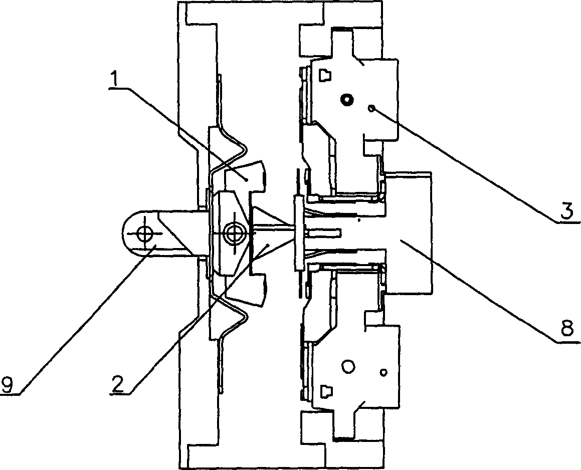
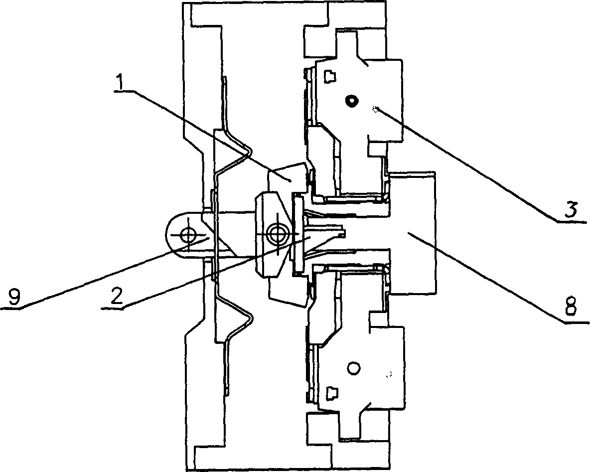
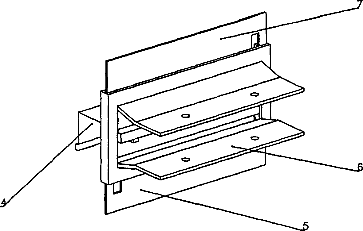
[0015] The shielded isolation circuit breaker of this embodiment is as figure 1 with figure 2 As shown, the T-shaped base 8 is relatively fixed to the circuit breaker housing, and the upper and lower static contacts 3 are respectively symmetrically fixed on its upper and lower sides. The positions corresponding to the two static contacts are respectively the upper and lower moving contacts 2 in the shape of "[" connected to the driving mechanism 9. Driven by the driving mechanism, the moving contacts can move in the horizontal direction, respectively having figure 1 The closed contact position and figure 2 disengagement of the disconnected position. An isolating device 2 is installed between the upper and lower static contacts 3 .

[0016] The isolating device is image 3 with Figure 4 Shown, be made of support 6, upper telescopic plate 5, following telescopic plate 7 and flat push plate 4. The horizontal splint of the support 6 is fixed on the base 8, and the upper a...


PUM


Abstract

This invention relates to a shield isolation breaker including static contactors and a dynamic contactor, in which, an isolation device is set between the two static contactors at both sides containing a shell, a flex board and a flat-push board, the shell is fixed on the base, the flex board makes up of a moving pair with a flex leading groove on the surface, a flexible leading inclined plane inserted into the leading groove is set on the flat push board, the groove is matched with the narrow end of the plane corresponding to the contact position of the static and dynamic contactors and the contractive position to the shell, the groove is matched with the wide end of the plane against the off-contact position of the contactors and the extending position to the shell, which can either isolate the cavity between two sides of contactors or shield the arc between dynamic and static contactors in the process of arc suppression.

Description

technical field [0001] The invention relates to a circuit breaker, in particular to a circuit breaker equipped with an arc shielding isolation device, and belongs to the technical field of power supply control facilities. Background technique [0002] As far as the applicant knows, the existing circuit breaker includes static contacts fixed on both sides of the base, and moving contacts corresponding to the static contacts. There is no arc shielding device between the moving and static contacts, but only rely on the arc extinguishing chamber to eliminate the arc. . Therefore, there are negative effects such as the arc cannot be extinguished in time, or the arc is easily re-ignited after being extinguished, which greatly affects the electrical life of the contacts of the circuit breaker. In addition, since there is no isolation device between the upper and lower breakpoints (if it is a single-breakpoint circuit breaker, between the upper and lower outgoing line bars), the in...

Claims


Application Information

Patent Timeline
Patent Type & Authority Applications(China)
IPC IPC(8): H01H1/64H01H9/30
Inventor 王靖郑改红胡义琴
Owner JIANGSU DAQO KFINE ELECTRIC
Learn More