
Driving circuit of display device and method for driving the display device

A technology for driving circuits and display devices, used in static indicators, static memories, optics, etc., can solve the problems of insufficient data voltage charging and other problems

Active Publication Date: 2011-04-27
LG DISPLAY CO LTD
View PDF0 Cites 1 Cited by
  • Summary
  • Abstract
  • Description
  • Claims
  • Application Information

AI Technical Summary

Problems solved by technology

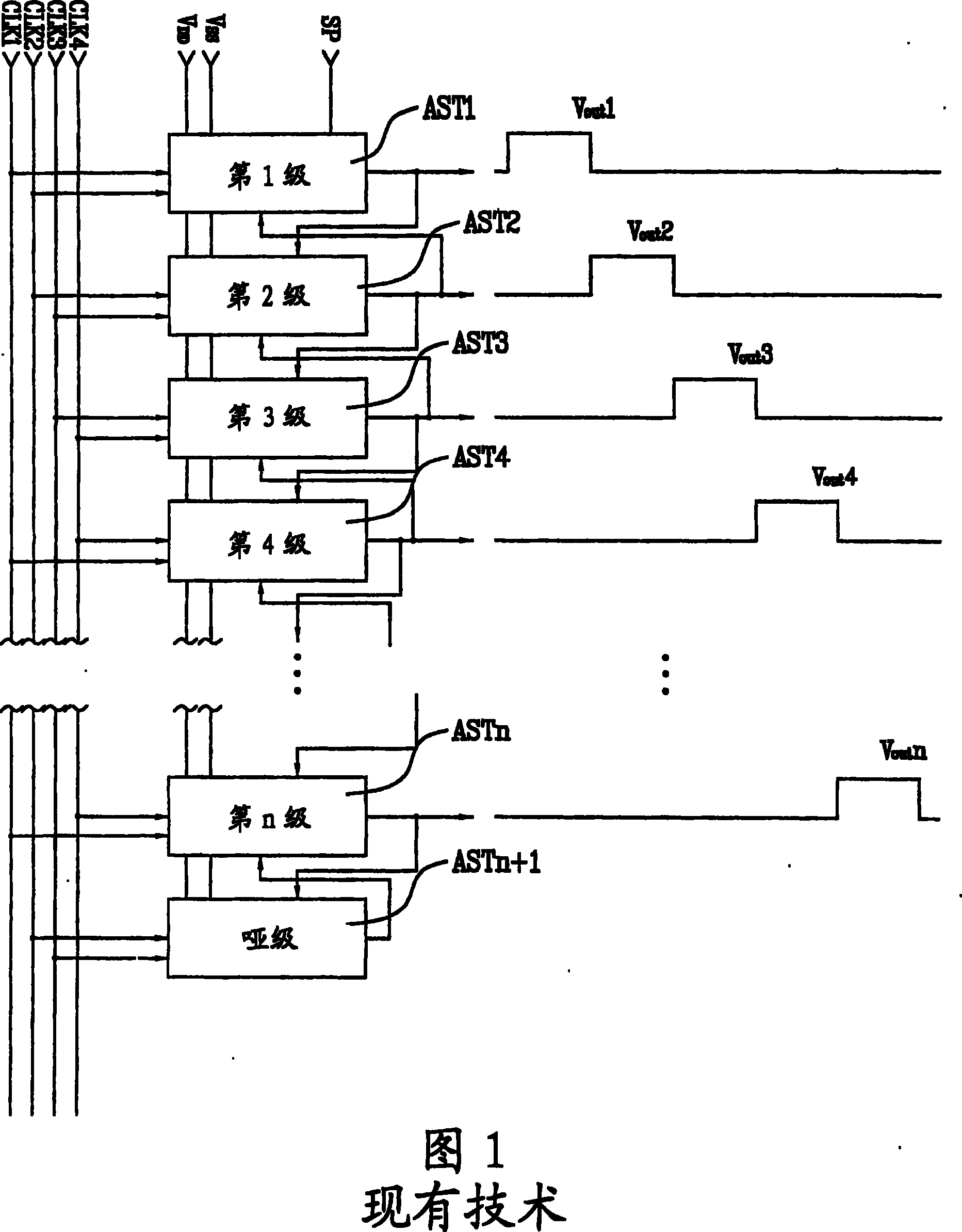
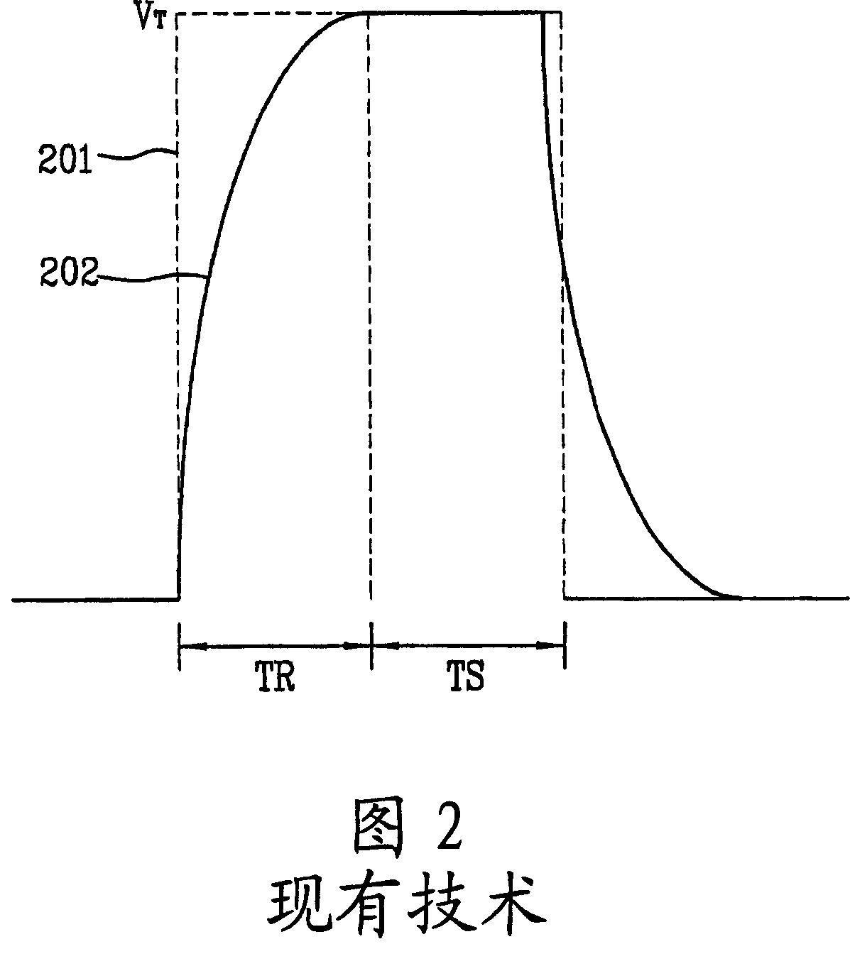
Therefore, there is a problem that the data voltage is not sufficiently charged into the pixel electrode

Method used


Image

  • Driving circuit of display device and method for driving the display device
  • Driving circuit of display device and method for driving the display device
  • Driving circuit of display device and method for driving the display device

Examples


Embodiment Construction

[0035] Hereinafter, preferred embodiments of the present invention will be described in detail, and examples thereof are illustrated in the drawings. As far as possible, the same reference numerals are used in all figures to refer to the same or similar parts.

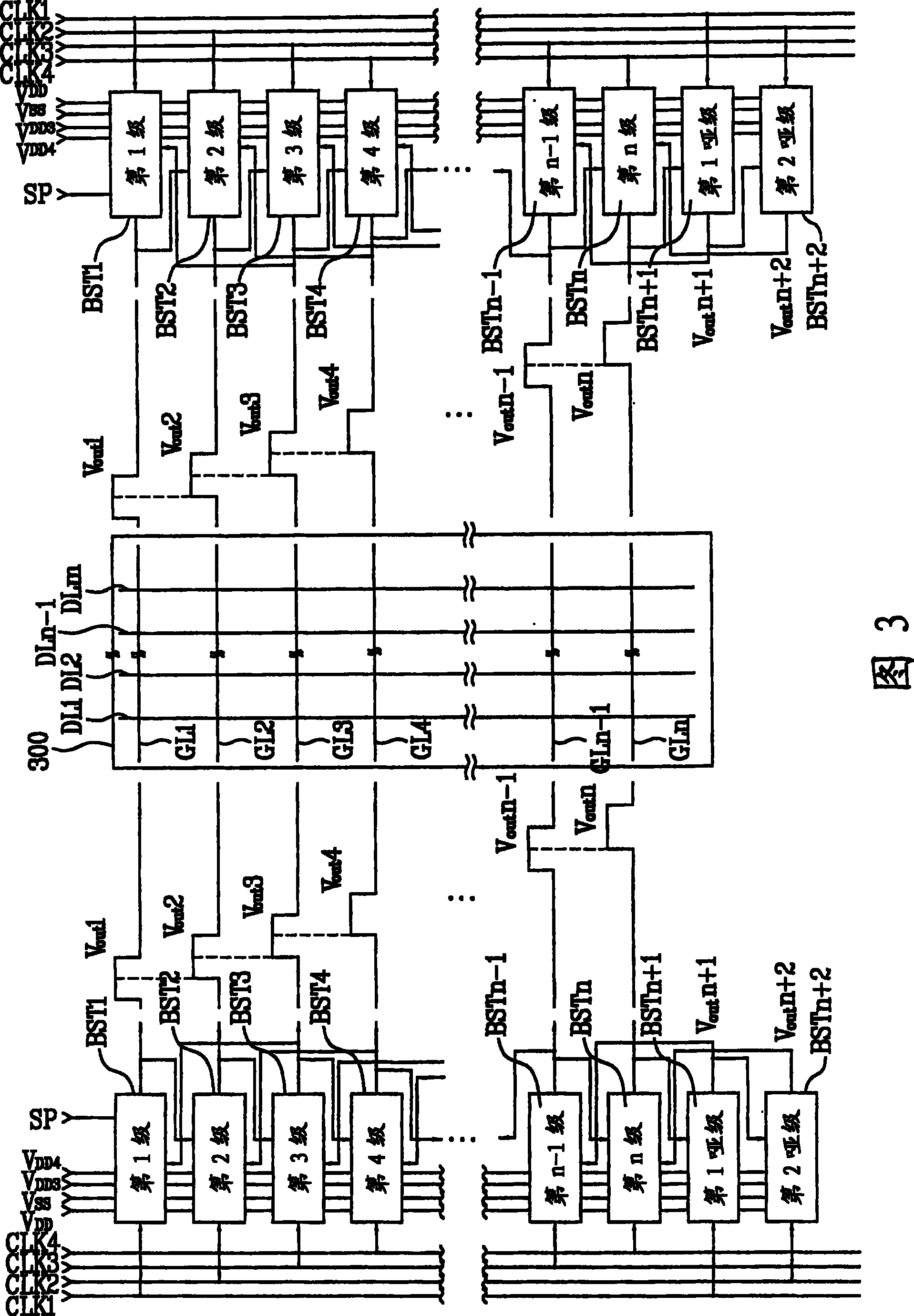
[0036] Fig. 3 is a block diagram illustrating the structure of a shift register according to the first embodiment of the present invention.

[0037] As shown in FIG. 3, the shift register according to the first embodiment of the present invention applied to the LCD device is characterized in that the shift register responds to an associated clock pulse among the clock pulses CLK1 to CLK4 and a start pulse, and press Sequentially output a plurality of scan pulses Vout1 to Voutn to the gate lines GL1 to GLn of the LCD panel 300, while increasing the pulse width of each of the plurality of scan pulses Vout1 to Voutn, so that the plurality of scan pulses The consecutive scan pulses in Vout1 to Voutn overlap each other for a pr...


PUM


Abstract

A driving circuit of a display device and a method for driving the display device are disclosed which are capable of reducing distortion of scan pulses supplied to gate lines of a liquid crystal panel. The driving circuit includes a first shift register for sequentially supplying first scan pulses to one-side ends of gate lines included in a display, respectively, to sequentially drive the gate lines, the first shift register simultaneously driving at least two adjacent ones of the gate lines for a predetermined period of time, and a second shift register for sequentially supplying second scan pulses to the other-side ends of the gate lines, respectively, to sequentially drive the gate lines, the second shift register simultaneously driving at least two adjacent ones of the gate lines fora predetermined period of time.

Description

Technical field [0001] The present invention relates to a drive circuit for a display device, and more specifically, to a drive circuit for a display device that can sequentially output a plurality of scan pulses with increased pulse widths, and make one of the plurality of scan pulses The continuous scanning pulses overlap each other for a predetermined time, thereby preventing the distortion of the scanning pulses. The present invention also relates to a driving method of such a display device. Background technique [0002] Typically, a liquid crystal display (LCD) device displays images by using an electric field to transmit light to liquid crystal. In order to realize this function, this type of LCD device includes an LCD panel having a plurality of pixel regions arranged in a matrix, and a driving circuit for driving the LCD panel. [0003] In the LCD panel, a plurality of gate lines and a plurality of data lines are arranged to cross each other. The pixel area of ​​the LCD ...

Claims


Application Information

Patent Timeline
Patent Type & Authority Patents(China)
IPC IPC(8): G09G3/36G09G3/20G02F1/133
CPCG09G3/3677G11C19/28G09G2310/0205G09G2320/0223G09G3/36G02F1/133
Inventor 张容豪金彬尹洙荣
Owner LG DISPLAY CO LTD
Learn More