
Hinge housing for a door leaf at least by areas made of a thin-walled metal or hollow metal profile

A door leaf and thin-walled technology is applied in the field of hinge shells used for door leaves at least partially composed of thin-walled metal or metal hollow profiles, and can solve problems such as damage to the firm fit and reliable fixation of the hinge shell, and labor-intensive problems.

Inactive Publication Date: 2007-01-03
KARL LAUTENSCHLAGER GMBH & CO KG
View PDF2 Cites 3 Cited by
  • Summary
  • Abstract
  • Description
  • Claims
  • Application Information

AI Technical Summary

Problems solved by technology

However, this screwing process is labor-intensive, and the threads of the fixing screws in the fixing dowels or - if not there - in the walls of the door leaf fixing holes after the metal parts and linings have been loosened and reconnected many times Threaded sliders, thereby compromising the secure fit and secure retention of the hinge housing on the door leaf

Method used


Image

  • Hinge housing for a door leaf at least by areas made of a thin-walled metal or hollow metal profile
  • Hinge housing for a door leaf at least by areas made of a thin-walled metal or hollow metal profile
  • Hinge housing for a door leaf at least by areas made of a thin-walled metal or hollow metal profile

Examples


Embodiment Construction

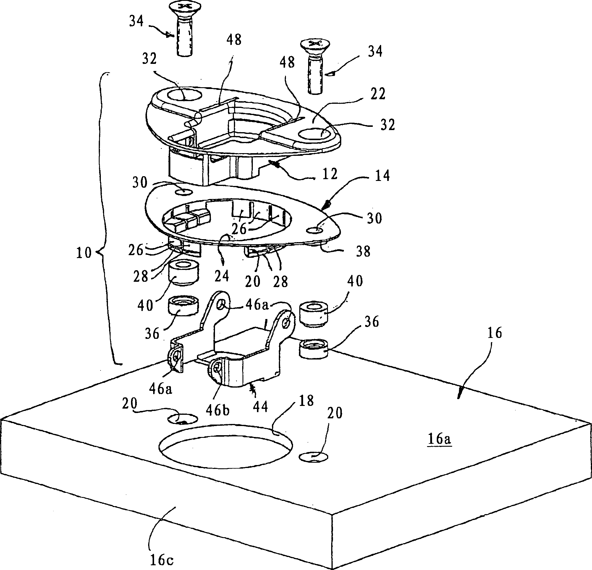
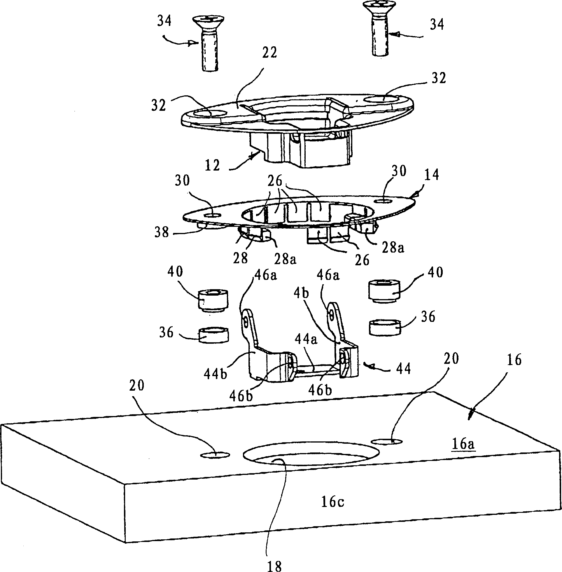
[0019] The hinge housing shown in the figure generally indicated by 10 is made of a metal, especially combined below figure 2 with 3 The cup 12 and a plastic backing 14 are further described in detail. The hinge housing 10 forms the leaf stop of an otherwise not shown hinge, in particular a four-joint hinge, by means of which the sheet metal door leaf 16 is articulated pivotably on the cone.

[0020]The hinge housing 10 is intended to be embedded and fixed in the double-walled edge region of the door leaf 16, wherein the inner wall of the door body when the door leaf is closed is designated by 16a, and the outer wall is designated by 16b, which are held by the end wall 16c constituting the lateral boundary of the door leaf. The smaller prescribed distance results in a relatively flat cavity between walls 16a and 16b.

[0021] In order to fix the hinge housing 10, on the wall 16a, especially on the figure 2 with 3 punched or drilled through-holes as shown in , that is to sa...


PUM


Abstract

The invention relates to a hinge housing (10) which is flushly mounted in a recess (18) inside the wall (16a) of a door leaf (16) which is made of a thin-walled metal and provided with a metal pot-shaped part (12) whose top edge is projected and forms in single-piece a fixing flange (22) and a guard plate (14) disposed between the fixing flange (22) and the internal part of the door leaf. Said guard plate (14) comprises elastic snap-in pins (26) which are disposed in the a recess (24) thereof corresponding to the recess (18) of the door leaf (16) and which, in the fixed position thereof, encompass the edge area of the recess (18) of the door leaf (16) on the internal part of the wall. Said guard plate (14) comprises at least two through holes which are (30) remote from each other in the direction of an opening (20) associated with each of them and embodied in the wall (16a) of the door leaf (16) and two through openings (32) which are embodied in the fixing flange (22) and are crossed by the butt-joints (34b) of fastening screws (34) whose ends are screwed into a clamping plate (36). Elastically deformable fixing bodies (40) crossed by the butt-joints (34b) of the fastening screws (34) are arranged between the flat faces of the guard plate (14) oriented towards the wall (16a) of the door leaf (16) and the limiting faces of the clamping plates (36) opposite thereto and in the undistorted form thereof produce an external limitation of the openings (20) in the wall (16a) of the door leaf and of the clamping plate 36.

Description

technical field [0001] The invention relates to a hinge housing designed as a cup-shaped insert which can be sunk-mounted in a hole inside the wall of the installation area of ​​a door leaf made of thin-walled metal in a piece of furniture, having a cup-shaped cup made of metal A piece integrally protrudes from the upper edge of the cup-shaped piece. When the cup-shaped piece is installed in a predetermined position on the door leaf, it covers the fixed flange of the inner side of the door leaf close to the area of ​​the hole in the door leaf; it also has a set Between the fastening flange and the inner side of the door leaf, in the region of the hole in the door leaf, there is a backing plate with a corresponding hole for the passage of the cup and which can be fastened together with the hinge housing on the inner side of the door leaf. Background technique [0002] The hinge housing of a modern multi-joint furniture hinge of the type considered here is used as a leaf stop ...

Claims


Application Information

Patent Timeline
IPC IPC(8): E05D7/12E05D5/08E05D9/00
CPCE05D5/08E05Y2900/20E05D7/123E05Y2900/208Y10T16/554E05D9/00
Inventor T·埃贝尔
Owner KARL LAUTENSCHLAGER GMBH & CO KG
Learn More