Rotor mechanical device
A mechanical device and rotor technology, which is applied in the field of mechanical principles and mechanisms, can solve the problems that the distance cannot be kept constant, the components driven by the rotor cannot be guaranteed, and the vibration amplitude of the disc rotor cannot be changed, so as to eliminate the influence of ellipticity and influence , to eliminate the effect of length variation
- Summary
- Abstract
- Description
- Claims
- Application Information
AI Technical Summary
Problems solved by technology
Method used
Image
Examples
Embodiment 1
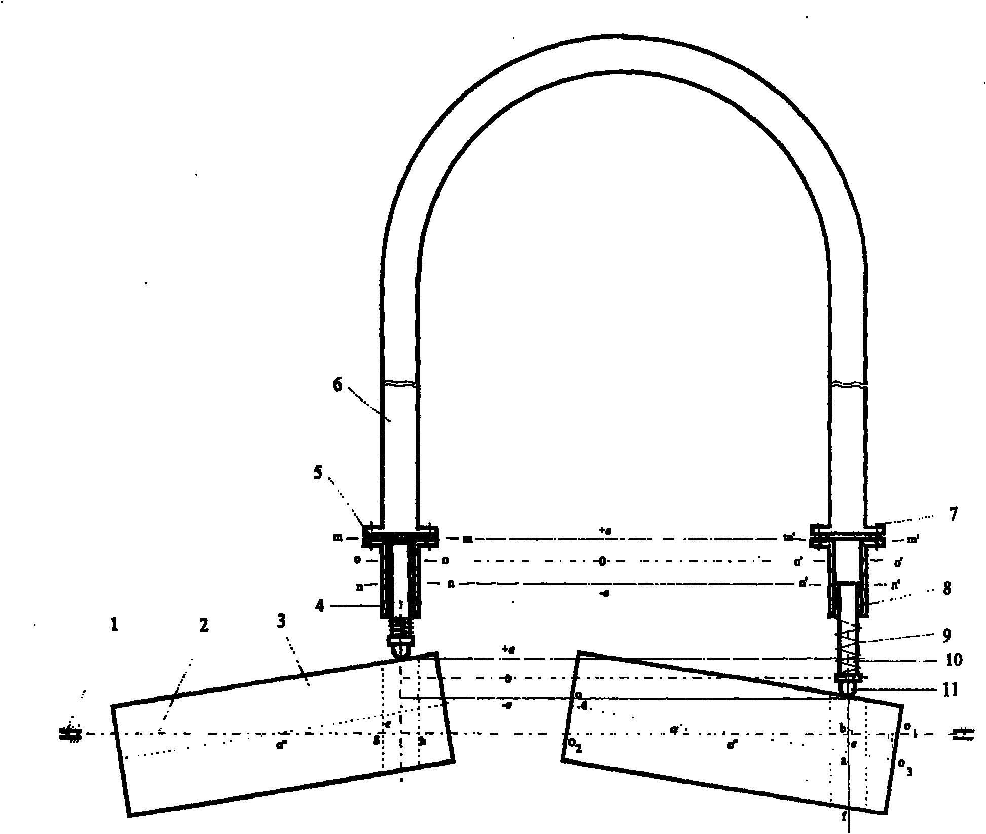
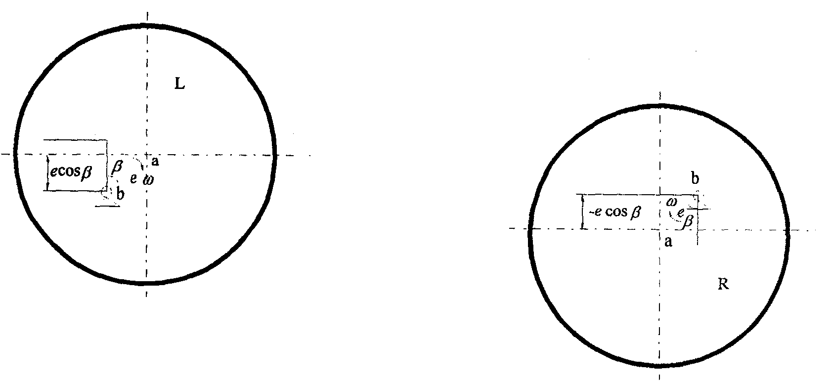
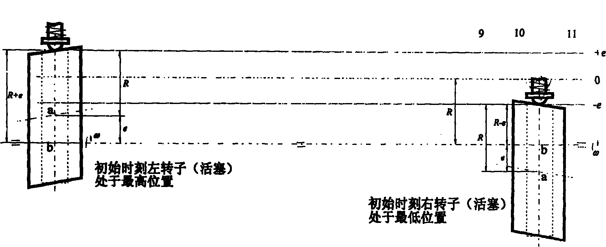
[0055] Embodiment 1, the curved equipment 6 is sealed and fixedly connected with the piston guide cylinder 4 through flanges, bolts, and gasket assemblies. The equipment 6 can be installed vertically or horizontally (this example is vertically installed). The piston 10 passes The sealing element and the piston guide cylinder 4 form a sealing movable fit, and the outer end of the piston 10 (which may be a piston rod if necessary) is in point contact with the rotor 3 . The cylindrical rotor 3 is driven by a power device (such as a motor). Since the geometric axis of the rotor 3 has an angle α with its rotation axis 2, there is an eccentricity in the rotor 3. The rotation of the rotor 3 pushes the piston 10 to reciprocate up and down, so that the equipment 6 The cavity space, so that the medium in the device 6 oscillates. In this example, the outer end of the piston 10 (which may be the piston rod if necessary) is in point contact with the rotor 3, so the motion of the piston 10 ...
Embodiment 2
[0056] Embodiment 2, to overcome the ellipticity influence caused by the inclination of the rotor 3, keep the size of the inner cavity space of the device 6 (that is, the distance between the inner end faces of the two pistons 10) constant, and make the piston 10 and the center of the rotor 3 For the same simple harmonic vibration, a contact piece 12 perpendicular to the centerline of the piston 10 (or the axis of the rotor 3 or the rotating shaft 2) can be added to the outer end of the piston 10 (if necessary, the piston rod), and the contact piece 12 is formed by the contact piece 12 and the rotor 3. Tangential contact, all the other are with embodiment 1. refer to figure 1 , Figure 38 , Figure 39 with Figure 40 .
Embodiment 3
[0057] In Embodiment 3, the circular section rotor 3 in Embodiment 1 is replaced with a cam rotor 3, and the rest are the same as Embodiment 1. refer to figure 1 , Figure 43 . When the piston 10 is in contact with the cam rotor 3, several commonly used motion forms of the piston 10 are:
[0058] 1) Isokinetic motion
[0059] Push distance: return trip:
[0060] 2) Equal acceleration and deceleration motion
[0061] Thrust (set as constant acceleration): Return trip (set to constant deceleration):
[0062] 3) Sine acceleration motion
[0063] a δ 0 ( 2 π δ 0 δ )
[0064] 4) Cosine accelerated motion
[0065] u = πa 2 δ 0 ( π δ 0 ...
PUM
 Abstract
Description
Claims
Application Information
 - R&D
- Intellectual Property
- Life Sciences
- Materials
- Tech Scout
- Unparalleled Data Quality
- Higher Quality Content
- 60% Fewer Hallucinations
Browse by: Latest US Patents, China's latest patents, Technical Efficacy Thesaurus, Application Domain, Technology Topic, Popular Technical Reports.
© 2025 PatSnap. All rights reserved.Legal|Privacy policy|Modern Slavery Act Transparency Statement|Sitemap|About US| Contact US: help@patsnap.com


