A range image sensor

A distance image and sensor technology, applied in the field of distance image sensors, can solve problems such as difficult saturation, drop of light detection elements, and difficulty in obtaining distance

Inactive Publication Date: 2006-10-04
MATSUSHITA ELECTRIC WORKS LTD
View PDF1 Cites 7 Cited by
  • Summary
  • Abstract
  • Description
  • Claims
  • Application Information

AI Technical Summary

Problems solved by technology

However, the light detection element becomes prone to saturation in environments that include a lot of ambient light noise (such as sunlight)
On the other hand, if the accumu

Method used


Image

  • A range image sensor
  • A range image sensor
  • A range image sensor

Examples


Example Embodiment

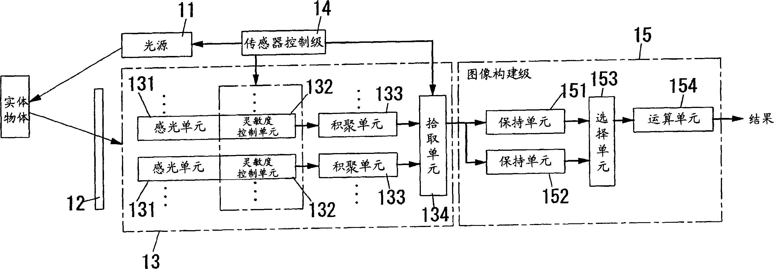
[0037] figure 1 A distance image sensor according to a first embodiment of the present invention is shown. The sensor comprises a light source 11 , an optical system 12 , a light detection element 13 , a sensor control stage 14 and an image construction stage 15 .

[0038] The light source 11 is constructed with, for example, an LED array arranged on a plane, a semiconductor laser, a diverging lens, etc., so as to provide sufficient light intensity. like figure 2 As shown, the light source 11 modulates the light intensity I according to a modulation signal of a specific frequency from the sensor control stage 14 1 , to emit sinusoidal intensity-modulated light into object space. However, it is not limited thereto, and the intensity waveform of the intensity-modulated light may be, for example, a triangular wave, a sawtooth wave, or the like. In addition, the light source 11 may include an infrared LED array, an infrared semiconductor laser, a diverging lens, and the like....


PUM


Abstract

A range image sensor comprising a light source, a light detecting element, a sensor control stage and an image construction stage. The image construction stage calculates a distance value for each image element in a range image based on each electric charge picked up after a specific detection period of different detection periods by the sensor control stage, and then constructs the range image. The specific detection period is one of one or more detection periods during which the light detecting element does not reach saturation, and is one detection period during which a value related to the quantity of light received from the object space becomes maximum of that of the one or more detection periods.

Description

technical field [0001] The present invention relates to a range image sensor (range image sensor), which is used to capture an image of an object space to generate a range image. In the range image, when there is at least one solid object in the object space, each image element (image element) includes The corresponding distance value from the entity object. Background technique [0002] The displacement measuring device described in Japanese Laid-Open Patent Publication No. H09-257418 scans a light beam irradiated to an object to be measured and then measures the distance from the displaced surface of the object with respect to a reference surface of the object based on triangulation. [0003] However, this device is not suitable for applications such as tracking the trajectory of the motion of a solid object in object space. Because it is necessary to scan the entire object space with the light beam in order to track the trajectory, and it takes a long time for the device...

Claims


Application Information

Patent Timeline
IPC IPC(8): G01S7/493H01L27/148G01B11/00G01C3/06G01S17/36G01S17/89H01L27/146H04N5/335H04N5/353H04N5/357H04N5/3725
Inventor 栗原史和高田裕司桥本裕介常定扶美
Owner MATSUSHITA ELECTRIC WORKS LTD
Why Eureka
Try Eureka