Barrier device, auto stereoscopic display using the same and driving method thereof

A partition and driver technology, applied in stereo systems, static indicators, instruments, etc., can solve the problems of not displaying 3D images correctly, narrow viewing angles, and difficulty in popularizing 3D image display devices.

Inactive Publication Date: 2006-09-06
SAMSUNG DISPLAY CO LTD
View PDF0 Cites 26 Cited by
  • Summary
  • Abstract
  • Description
  • Claims
  • Application Information

AI Technical Summary

Problems solved by technology

[0009] However, although the sawtooth partition improves horizontal resolution, it suffers from a narrow viewing angle
Also, although it can be used for both the portrait mode screen and the landscape mode screen, when the screen is changed to landscape mode while the display mode of the partition is fixed, due to the position of the left eye pixel and the right eye pixel of the display panel, and the position of the opaque and transparent areas of the divider, may not display the 3D image correctly
[0010] For those reasons, it has been difficult to popularize 3D image display devices so far

Method used


Image

  • Barrier device, auto stereoscopic display using the same and driving method thereof
  • Barrier device, auto stereoscopic display using the same and driving method thereof
  • Barrier device, auto stereoscopic display using the same and driving method thereof

Examples


Embodiment Construction

[0047] Some exemplary embodiments of the present invention will be described in detail below with reference to the accompanying drawings.

[0048] In the following detailed description, only some exemplary embodiments of the invention have been shown and described, simply by way of example. As those skilled in the art would realize, the described embodiments may be modified in various different ways, all without departing from the spirit or scope of the present invention. Accordingly, the drawings and descriptions are to be regarded as illustrative in nature and not restrictive. Throughout the specification, the same reference numerals denote the same elements.

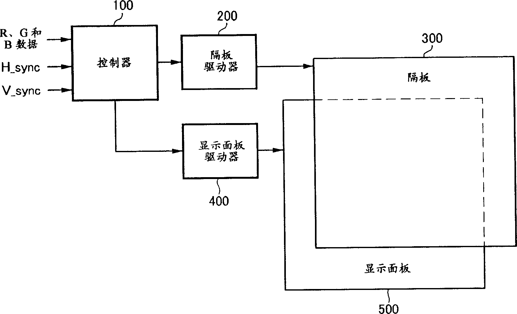
[0049] figure 1 A block diagram showing a 3D image display device according to an exemplary embodiment of the present invention.

[0050]The 3D image display device includes a controller 100 , a spacer driver 200 , a spacer 300 , a display panel driver 400 and a display panel 500 .

[0051] The controller 100 gene...


PUM


Abstract

A 3D image display device includes a display panel, a barrier, a controller, and a barrier driver. The barrier includes: a first substrate; a plurality of first electrodes disposed on the first substrate and extended in a first direction; a plurality of second electrodes respectively disposed between adjacent first electrodes; a second substrate opposing the first substrate; a plurality of third electrodes disposed on the second substrate and extended in a second direction crossing the first direction; a plurality of fourth electrodes respectively disposed between adjacent third electrodes; and a liquid crystal layer disposed between the first and second substrates. The barrier driver receives a barrier control signal from the controller, and applies a reference voltage to the first electrodes, the second electrodes, the third electrodes, and / or the fourth electrodes, and applies a liquid crystal driving voltage to one or more other ones of the first to fourth electrodes.

Description

technical field [0001] The present invention relates to a spacer device and a 3D image display device using the same for displaying a 3D image by utilizing binocular parallax. More specifically, the present invention relates to a spacer device and a 3D image display device using the same and capable of changing the shape of the spacer. Background technique [0002] Generally, people perceive the stereoscopic effect physiologically and empirically. In the three-dimensional image display technology, a stereoscopic effect of an object is generated by using binocular parallax, and binocular parallax is a main factor for seeing the stereoscopic effect at a short distance. Stereoscopic images can be viewed through a stereoscopic method that requires glasses or an autostereoscopic method that does not require glasses. [0003] The anaglyph method is divided into an anaglyph method, a polarization method, and a time division method, wherein the anaglyph method involves wearing gla...

Claims


Application Information

Patent Timeline
Patent Type & Authority Applications(China)
IPC IPC(8): G02B27/22G02F1/133G09G3/36
CPCH04N13/0409H04N13/0497H04N13/31H04N13/398E05Y2800/41E06B3/02E06B7/215E06B7/36
Inventor 南熙李璋斗张亨旭金范植宋明燮
Owner SAMSUNG DISPLAY CO LTD
Why Eureka
Try Eureka