Liftable deep well false bottom system

A technology for deep wells and mooring devices, which is applied to ship components, measuring devices, instruments, etc., and can solve problems such as

Active Publication Date: 2006-09-06
SHANGHAI JIAO TONG UNIV
View PDF0 Cites 15 Cited by
  • Summary
  • Abstract
  • Description
  • Claims
  • Application Information

AI Technical Summary

Problems solved by technology

At the same time, using a simple pneumatic clamping device to hold the steel column installed under the false bottom to lock the position of the false bottom will make the steel column under the false bottom reach tens of meters in length. How to ensure its rigidity and processing accuracy is critical big technical problem
In further searches, there are no literature reports identical or similar to the subject of the present invention

Method used


Image

  • Liftable deep well false bottom system
  • Liftable deep well false bottom system
  • Liftable deep well false bottom system

Examples


Embodiment Construction

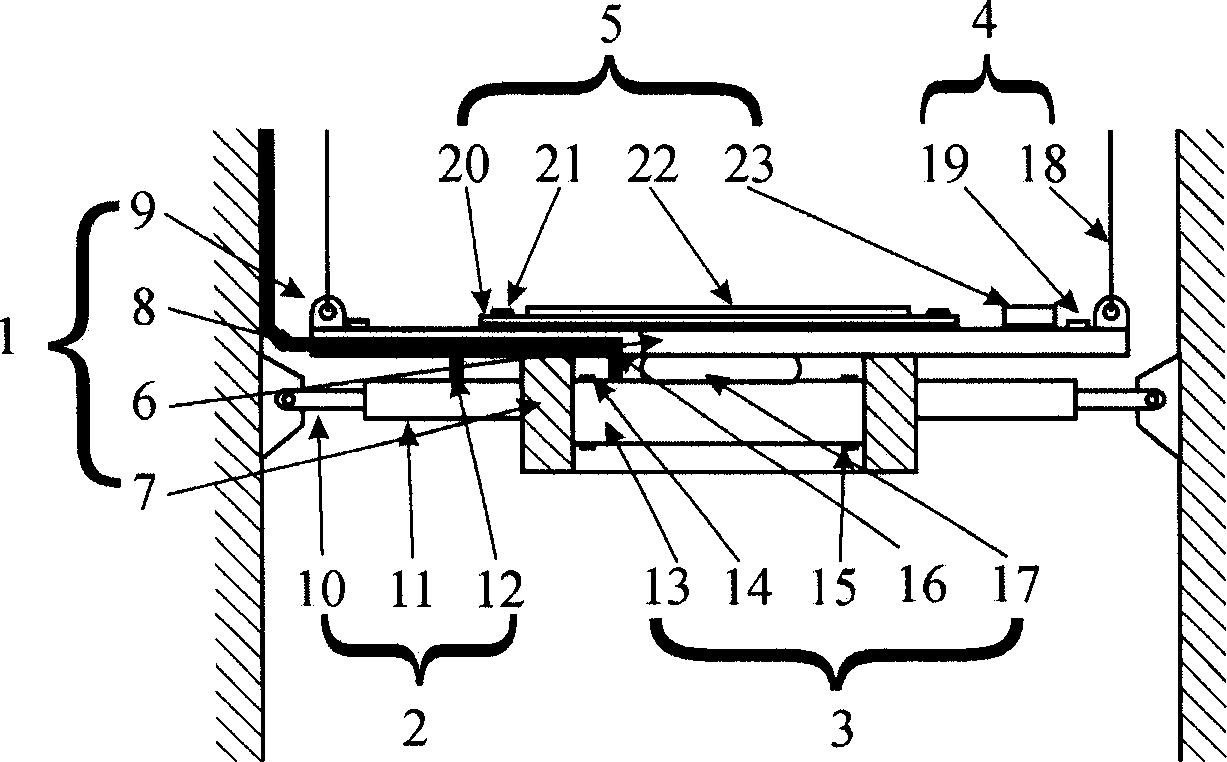
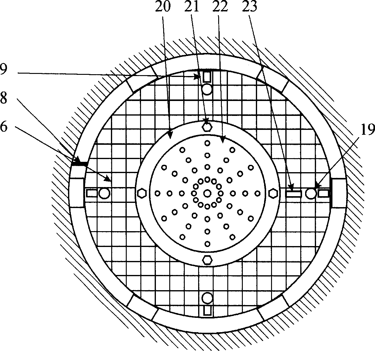
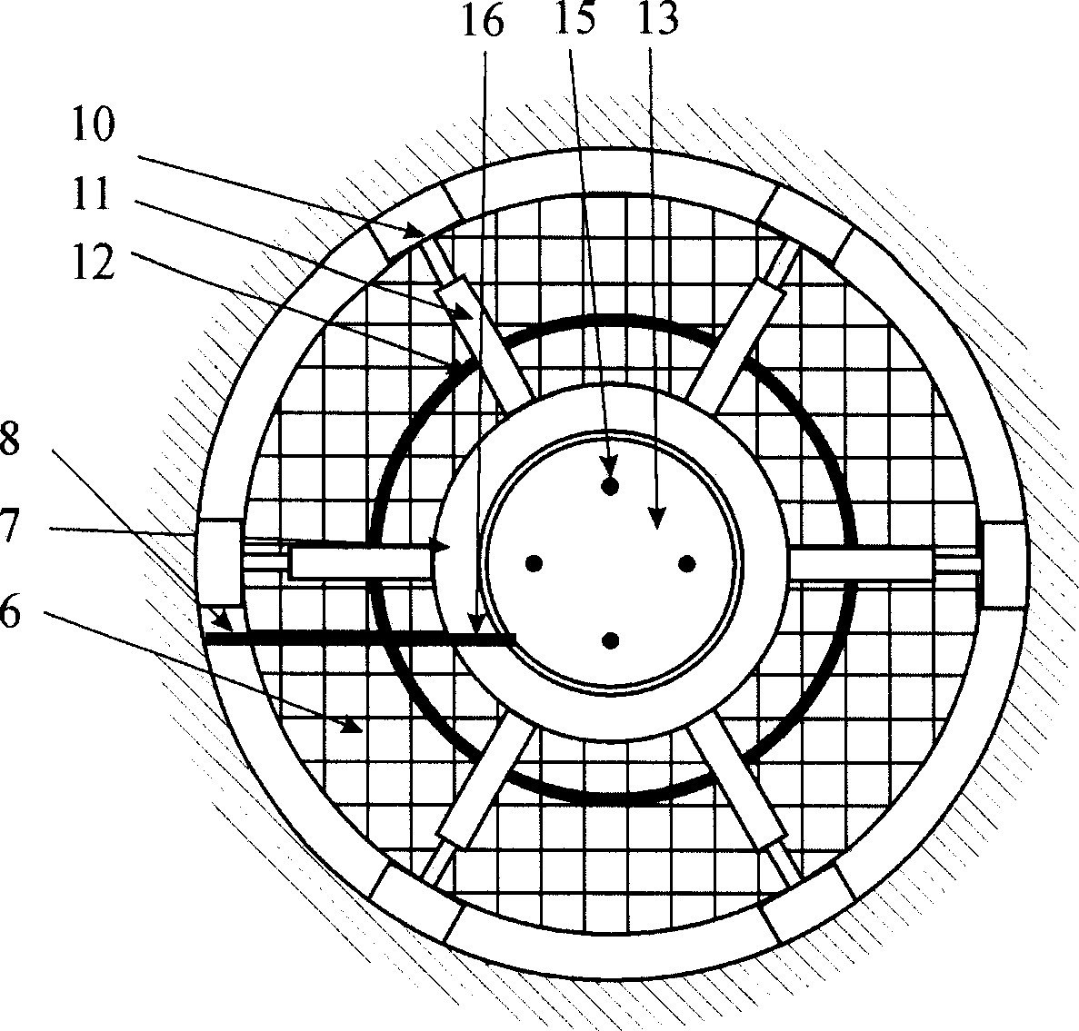
[0018] Such as Figure 1-3 As shown, the present invention includes: a deep well false bottom structure main body 1, a position locking device 2, a buoyancy adjusting device 3, a lifting device 4, and a mooring device 5 for experiments. The main body of the deep well false bottom structure 1 serves as the main frame of the entire deep well false bottom structure. A total of six sets of position locking devices 2 are arranged around the bottom of the deep well false bottom structure main body 1, and the buoyancy adjustment device 3 is arranged at the center of the bottom of the deep well false bottom structure main body 1. A mooring device 5 for experiments is installed in the middle of the upper surface of the main frame of the false bottom of the deep well, and a lifting device 4 is installed around it.

[0019] The deep well false bottom structure main body 1 includes: vertical and horizontal beam system 6 , circular frame 7 , compressed air supply pipeline 8 , and lifting p...


PUM


Abstract

The system comprises: a body as the main frame, six set of position lock devices arranged round the body, a buoyancy regulation device on bottom center, some lifting devices, and an experimental mooring device on center of main frame top surface. This invention can meet deep-sea testing request.

Description

technical field [0001] The invention relates to equipment in the field of ships and marine engineering, in particular to a false bottom system for a deep well that can be lifted. Background technique [0002] The water depth of various parts of the ocean varies with different locations, from a few meters in the offshore to a depth of 10,000 meters in the deep sea, and the depth varies widely. In the ship and ocean engineering model test, in order to simulate the water depth of different sea areas, it is necessary to conveniently adjust the water depth during the test in the pool. Since ocean engineering tests mostly use models with a large scale ratio for the tests, the accuracy of the water depth of the pool is required to be very high. The water depth of marine engineering pools is generally adjusted by adjusting the position of the large-area floating false bottom installed in the pool. The false bottom is a large floating body structure floating in the pool, and its bu...

Claims


Application Information

Patent Timeline
Patent Type & Authority Applications(China)
IPC IPC(8): G01M10/00B63B9/02B63B71/20
Inventor 杨建民李润培彭涛张承懿
Owner SHANGHAI JIAO TONG UNIV
Why Eureka
Try Eureka