
Display device

A technology for display devices and display components, which is applied to identification devices, carrier indication/alarm devices, instruments, etc., and can solve the problems that users cannot see the display window, large area, high height, etc.

Inactive Publication Date: 2006-07-05
LEJIN GUANGDIAN ELECTRONIC CO LTD SHANGHAI
View PDF0 Cites 2 Cited by
  • Summary
  • Abstract
  • Description
  • Claims
  • Application Information

AI Technical Summary

Problems solved by technology

Therefore, the installation of electronic equipment requires a large area, and it cannot be adapted to the installation of various environments.
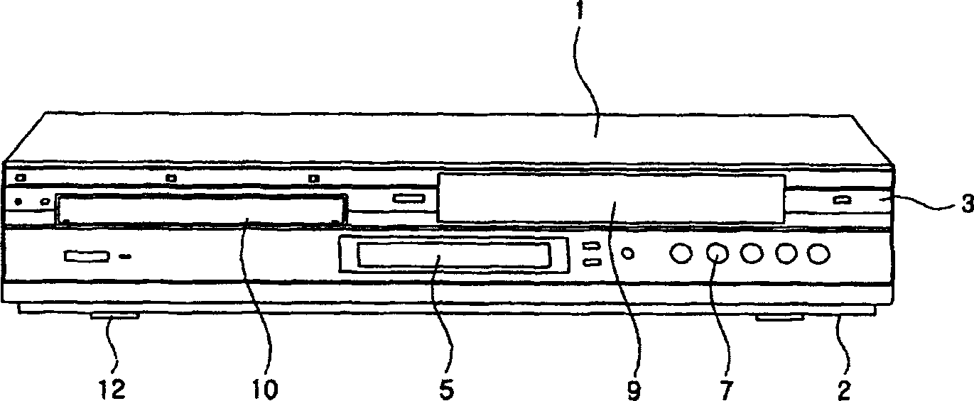
[0009] In particular, the left and right sides of the front end of the existing electronic equipment casing 1 are relatively wide, and if one side of the casing 1 supports the bottom surface, its height will be too high.
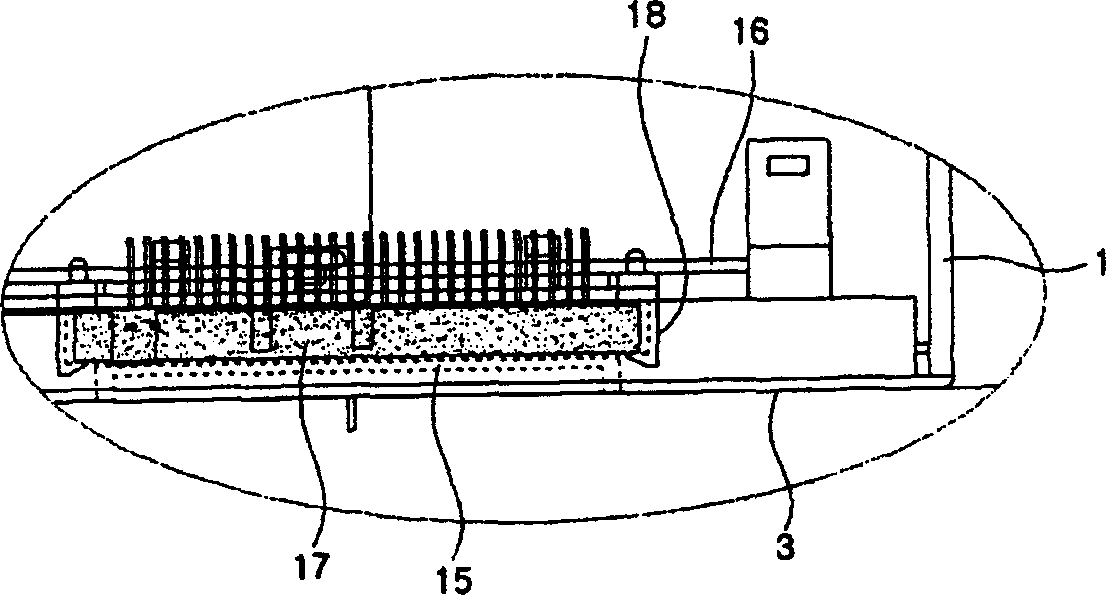
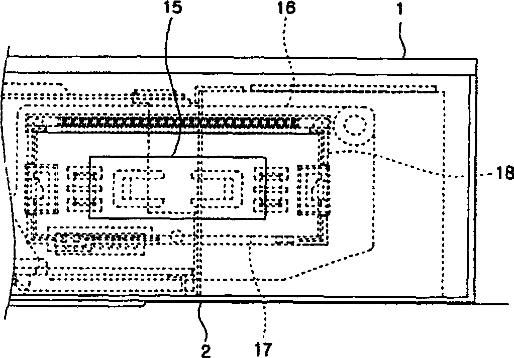
[0010] At the same time, even though the existing electronic equipment can be arranged in various ways, in the front of the electronic equipment, the user cannot see the display window 15 of the display device 5, which affects the convenience of the user. The reason why the digital readout nixie tube 17 of device 5 is fixed on the circuit board according to the support frame

Method used


Image

  • Display device
  • Display device
  • Display device

Examples


Embodiment Construction

[0044] Embodiments of the display device of the present invention will be described in detail below with reference to the accompanying drawings.

[0045] image 3 is a schematic diagram of an embodiment of a display device according to the present invention, Figure 4 is a schematic diagram of an electronic device suitable for a display device according to an embodiment of the present invention, Figure 5 is a configuration cross-sectional view of an electronic device equipped with a display device according to an embodiment of the present invention.

[0046] As shown in the figure, the display device 20 according to the embodiment of the present invention is configured with two ends of a rotating housing 24 rotatably supported by supporting legs. The above-mentioned support legs 22 are equipped at both ends of the rotating housing 24, for example, fixed to the lower housing 40 of the electronic equipment and the like.

[0047] There can be various configurations for fixing...


PUM


Abstract

The invention relates to a display unit, comprising: a rotating casing with a front opening; a support leg for supporting the rotating casing in rotating mode; a gravity drop hammer arranged on one side of the rotating casing; and an information display element exposed at the front opening. An electronic device equipped with the display unit can be set into different styles, but the display contents of the display unit are processed in a certain direction, therefore improving the convenience of users.

Description

(1) Technical field [0001] The invention relates to a display device, in particular to a display device for displaying the operating state of electronic equipment. (2) Background technology [0002] figure 1 It is a schematic front view of the structure of the electronic device according to the prior art. As shown in the figure, the housing of an electronic device is mainly composed of a casing 1 and a chassis 2 . The cabinet 1 constitutes the upper surface and both sides of the display, and the chassis 2 constitutes the lower surface. [0003] A front panel 3 forming the front of the display is provided at the front end of the cabinet 1 . A display device 5 for displaying and displaying an operating state and an operating device 7 for operating the display are provided in the front panel 3 . Various keys are provided in the above-mentioned operating device 7 . [0004] On the other hand, one side of the front panel 3 is equipped with a cassette compartment door 9 for o...

Claims


Application Information

Patent Timeline
Patent Type & Authority Applications(China)
IPC IPC(8): G11B33/10G09F9/00
Inventor 金天宁
Owner LEJIN GUANGDIAN ELECTRONIC CO LTD SHANGHAI
Learn More