
Spanner

A wrench and head technology, applied in the field of work tools, can solve problems such as difficult work, achieve high work efficiency, and improve work speed and efficiency.

Inactive Publication Date: 2006-06-28
WORLDVISION
View PDF0 Cites 3 Cited by
  • Summary
  • Abstract
  • Description
  • Claims
  • Application Information

AI Technical Summary

Problems solved by technology

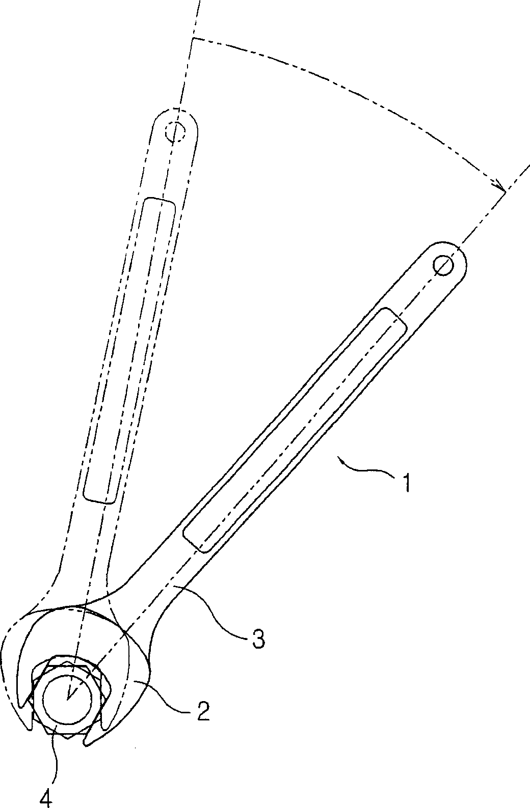
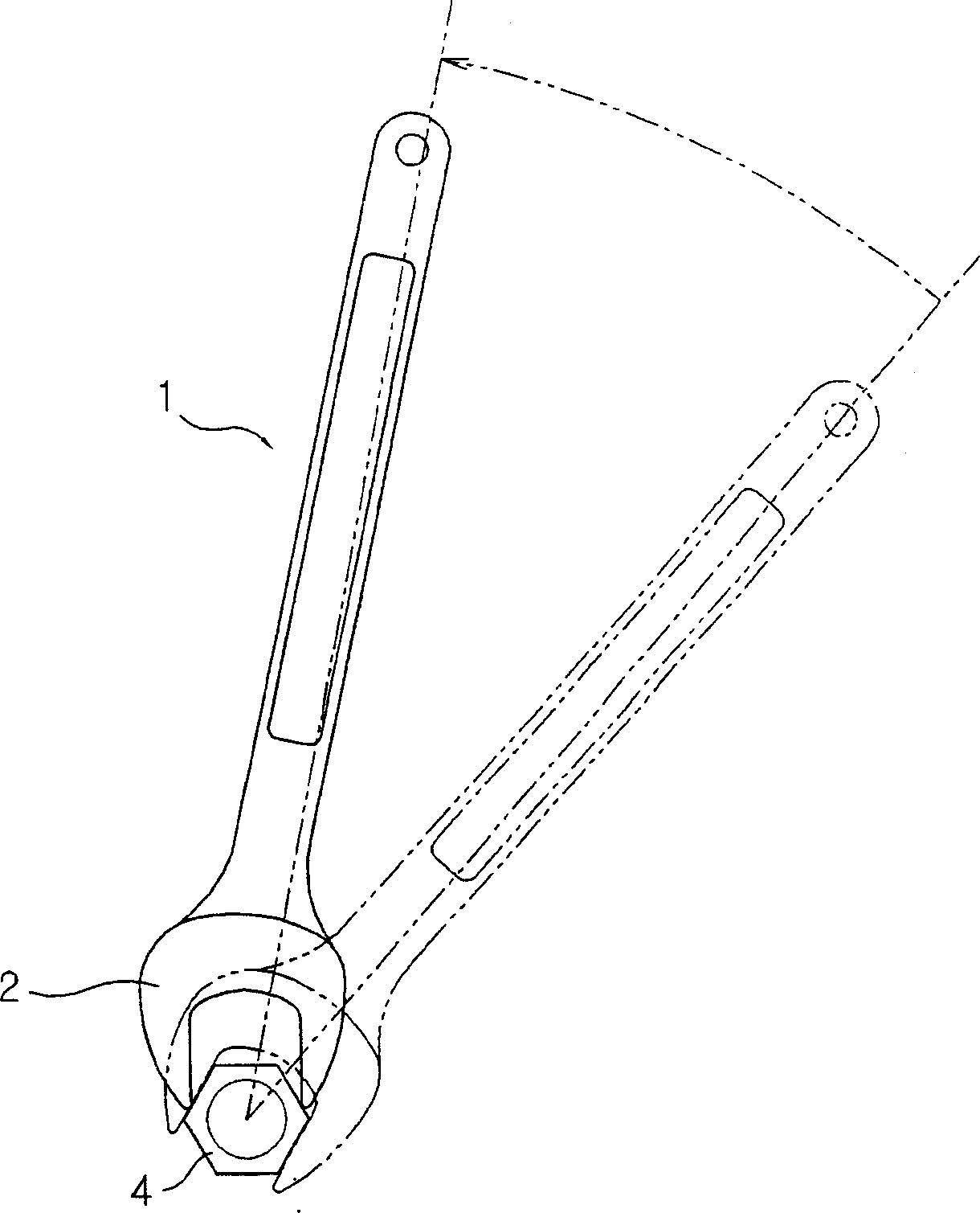
[0005] In the wrench 1 in the prior art, it is necessary to fit the wrench head 2 of the wrench 1 on the head of the bolt 4, rotate the handle 3 by a predetermined angle to carry out the work, and then pull out the wrench head from the bolt 4 again. Fit the wrench head 2 of the wrench 1 to the bolt 4, and repeat the operation
[0006] Additionally, if figure 2 As shown, when the wrench head 2 of the wrench 1 is combined with the head of the bolt 4, for the wrench head 2 of the wrench 1 to fit the bolt 4, a space of about 120° must be left for the wrench head 3 to rotate , it is difficult to work in a small space

Method used


Image

  • Spanner
  • Spanner
  • Spanner

Examples


Embodiment Construction

[0030] Hereinafter, embodiments of the present invention will be described in detail with reference to the drawings.

[0031] First of all, the terms and words used in the description and claims of the present invention are not limited to the meanings of the words explained in the dictionary. The inventor respects the principle of proper definition of terms in order to best describe the present invention, so it should be regarded as suitable for the present invention. Explain the meaning and concepts of invented technical ideas.

[0032] Therefore, the embodiments described in the present invention and the structure shown in the drawings are merely the best embodiments of the present invention, and do not include all the technical ideas of the present invention. Therefore, the present invention also includes various equivalents and modifications. .

[0033] image 3 It is a perspective view of a wrench according to an embodiment of the present invention.

[0034] With reference t...


PUM


Abstract

A wrench comprising: a wrench part for loosening or tightening an object body; a pair of wedge-shaped sliding pieces, which are symmetrically combined inside the wrench part, and between the wrench part and the object body Can move to the outside and slide back and forth between them; the coil spring, which is interposed between the inner bottom surface of the wrench head and the side of the sliding piece opposite to the inner bottom surface, elastically biases the sliding piece The sliding piece is elastically supported against the opening direction of the wrench portion. Since the wrench with this structure has a slidable sliding piece, even in a narrow space, it is not necessary to pull out the wrench head of the wrench, so that the work can be carried out continuously and smoothly, and the structure is improved.

Description

Technical field [0001] The invention relates to a working tool, particularly a wrench used for tightening or loosening bolts or nuts. Background technique [0002] Generally, a wrench is a tool used to tighten or loosen bolts or nuts and other fittings (Fitting), which are classified into various types according to their size and shape. [0003] Wrenches used to loosen or tighten bolts or nuts are generally used in the past. figure 1 and figure 2 The structure shown. [0004] Refer to figure 1 The part where the wrench 1 engages with the head of the bolt 4, that is, the wrench head 2 is opened in one side direction, and the handle 3 extended from the wrench head is rotated by a predetermined angle in one direction or the other reversely. And tighten or loosen bolt 4. [0005] In such a prior art wrench 1, it is necessary to fit the head 2 of the wrench 1 to the head of the bolt 4, rotate the handle 3 by a predetermined angle to perform work, and then pull out the head from the...

Claims


Application Information

Patent Timeline
IPC IPC(8): B25B13/12B25B13/46
CPCB25B13/12B25B13/481
Inventor 朴海洋朴浩根
Owner WORLDVISION
Learn More