Current detecting device and method

A technology of current detection and current value, applied in the field of current detection devices, can solve the problem that only the central processing unit can be displayed

Inactive Publication Date: 2006-06-07
GIGA BYTE TECH CO LTD
View PDF0 Cites 2 Cited by
  • Summary
  • Abstract
  • Description
  • Claims
  • Application Information

AI Technical Summary

Problems solved by technology

[0004] The main technical problem to be solved by the present invention is to provide a current detection device and method to solve the disadvantage of only displaying the voltage value of the central processing unit in the prior art, so that the user can, through the display value of a display unit, Clearly see the load current of the CPU at this time

Method used


Image

  • Current detecting device and method
  • Current detecting device and method
  • Current detecting device and method

Examples


Embodiment Construction

[0022] Specific embodiments of the present invention will be described in detail below in conjunction with the accompanying drawings.

[0023] In the prior art, since only the symbol voltage value of the central processing unit can be detected, the actual current value cannot be displayed. Therefore, the present invention provides that the user can clearly see the load current of the central processing unit at this time through the displayed value of a display unit.

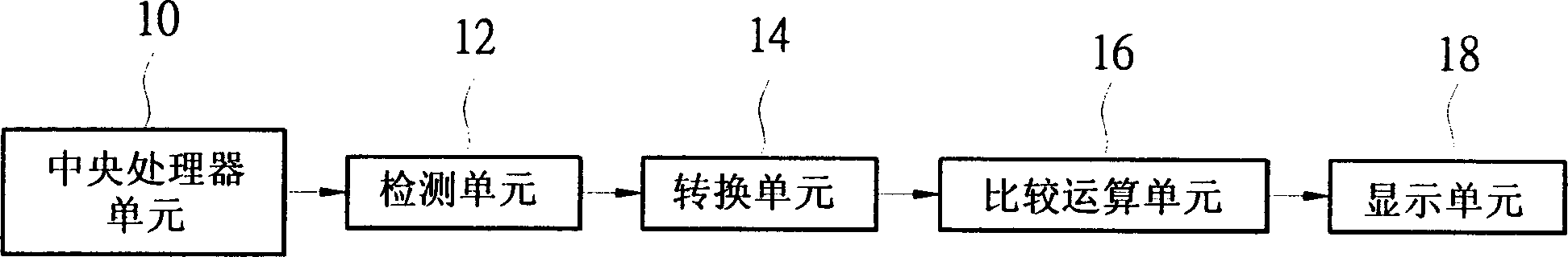
[0024] Such as figure 1 as shown, figure 1 It is a schematic diagram of a current detection device according to the first embodiment of the present invention, including: a central processing unit 10 for generating a current signal. A detection unit 12 is electrically connected to the CPU unit for detecting the current signal generated by the CPU unit. A conversion unit 14 is electrically connected to the detection unit to convert the current signal into a voltage value. A comparison operation unit 16 is elect...


PUM


Abstract

The present invention discloses current detecting device and method superior to available technology, which can show the voltage of CPU only. The current detecting device and method of the present invention can also show the load current of CPU definitely with LEDí»s, seven-segment display or display screen.

Description

technical field [0001] The invention relates to a current detection device and method, in particular to a method for measuring the magnitude of the current loaded by a central processing unit by using the current detection device. Background technique [0002] The basic output and input system of the motherboard has the function of setting the voltage of the central processing unit. The motherboard will generate a new voltage indicator signal according to the corresponding relationship between the set voltage and the voltage indicator symbol (VID) and pass it through the digital / analog converter. The voltage is converted into a reference voltage, and then the reference voltage is sent to the central processing unit, and finally the output voltage is equal to the set voltage value through the regulating circuit. When CPUs with different voltages are used, the motherboard will output the most appropriate voltage according to the CPU. [0003] The prior art can only detect the...

Claims


Application Information

Patent Timeline
Patent Type & Authority Applications(China)
IPC IPC(8): G01R19/165G01R19/25
Inventor 廖哲贤洪如怡
Owner GIGA BYTE TECH CO LTD
Why Eureka
Try Eureka