Process for the detection of vibrations of a roll stand

A roll machine and rack technology, which is applied in the field of detecting the vibration of roll racks, and can solve problems such as inability to distinguish racks

Inactive Publication Date: 2006-05-17
CLECIM SAS
View PDF2 Cites 13 Cited by
  • Summary
  • Abstract
  • Description
  • Claims
  • Application Information

AI Technical Summary

Problems solved by technology

The above proposed device can only detect the acoustic frequencies emitted by the stands of the tandem rolling mill as a whole, but cannot directly distinguish the stands from each other

Method used


Image

  • Process for the detection of vibrations of a roll stand
  • Process for the detection of vibrations of a roll stand
  • Process for the detection of vibrations of a roll stand

Examples


Embodiment Construction

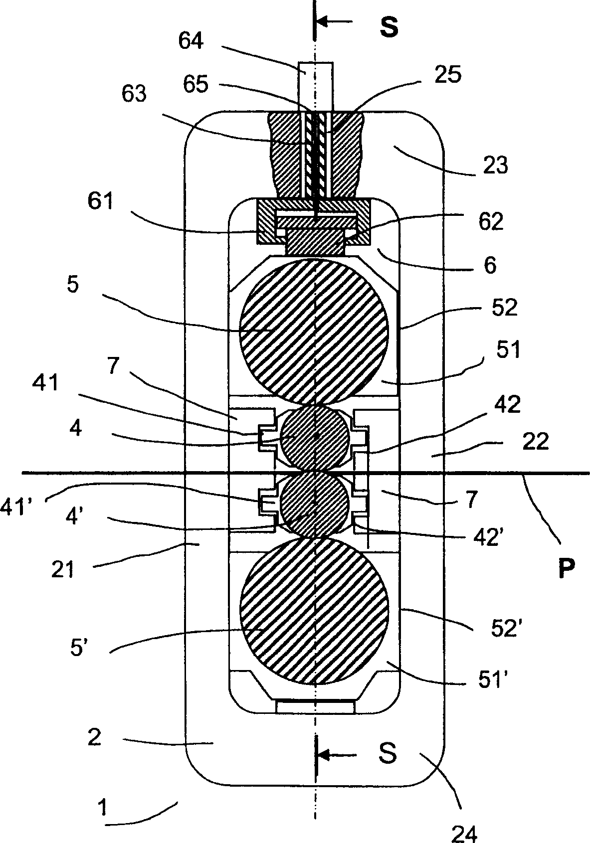
[0033] Such as figure 1 and figure 2 As shown, the roll stand 1 itself is a four-roll roll stand known to those skilled in the art, and it includes two support columns (support column) 2 and 2'. Support frames 2 and 2' are separated and connected by cross beams 3, 3' between which are arranged a set of superimposed rollers with parallel axes positioned substantially in line with the rolling mill. In the same adjustment plane S that is perpendicular to the moving direction of the material P.

[0034] Each shelf 2, 2' has a closed shape to form a ring and each shelf comprises two upright pillars 21, 22 (21', 22') and two horizontal parts 23, 24 (23', 24') .

[0035] The set of stacked rolls includes two work rolls 4, 4' and two backing rolls 5, 5', the rolling stock P passes through the middle of the work rolls 4, 4', and the work rolls rest against the backing rolls. On the roller 5, 5'.

[0036] Incidentally, it can be noted that besides the four-high roll stand, there are...


PUM


Abstract

The invention relates to a method for detecting vibrations of a roll stand (1). The roll stand (1) is equipped with a hydraulic jack (6) as a device for adjusting the rolls (4, 5). The hydraulic jack includes a sensor (64) providing a digital signal (POS) that measures the position of the movable part relative to the fixed part. According to the invention, vibrations are detected by directly observing the position signal (POS) and comparing it with a spatio-temporal window (F), the size of which is determined as a function of the frequency to be measured. According to the present invention, different observation windows (F) suitable for detecting different vibration phenomena can be determined. In a continuous rolling mill, the method of the invention makes it possible to observe the position signal (POS) of the hydraulic jacks (6) of each roll stand (1) and thus to detect the onset of vibration in each stand and to determine from which stand the phenomenon started .

Description

technical field [0001] The present invention relates to a method for detecting vibrations of roll stands during hot and cold rolling of various materials. The invention can be used in particular for the detection of thickness-influencing vibrations during the rolling of flat rolled stock in strip form, especially when tandem mills are used. Background technique [0002] Metallurgical products, especially flat rolled products (such as metal plates, rods, or strips), whether they are made of steel, aluminum, or other materials or alloys, usually by rolling using a mill The rolling mill is a rolling mill formed by at least one roll stand and, for example, a set of stands arranged in succession to form what is known as a tandem mill train. [0003] Typically, roll stands include large rotating masses, such as working and backing rolls, and reduction gears. These masses can start to vibrate without being noticed, especially during high-speed rolling. [0004] This phenomenon, ...

Claims


Application Information

Patent Timeline
Patent Type & Authority Applications(China)
IPC IPC(8): B21B38/00
CPCB21B37/007B21B37/62B21B38/008B21B38/00
Inventor 米歇尔·阿比·卡拉姆埃米利奥·洛佩斯·萨比奥
Owner CLECIM SAS
Why Eureka
Try Eureka