Boiling cooling device
A boiling cooling and refrigerant technology, applied in the direction of cooling/ventilation/heating transformation, refrigerators, refrigeration components, etc., can solve the problems of performance reduction, increase of refrigerant liquid level, reduction of effective area of heat dissipation part 120, etc.
- Summary
- Abstract
- Description
- Claims
- Application Information
AI Technical Summary
Problems solved by technology
Method used
Image
Examples
no. 1 Embodiment approach
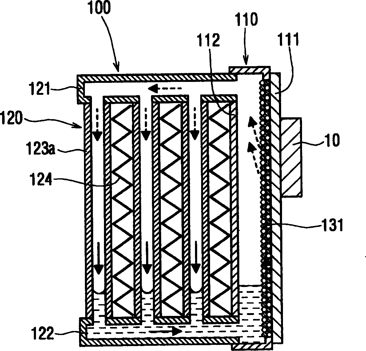
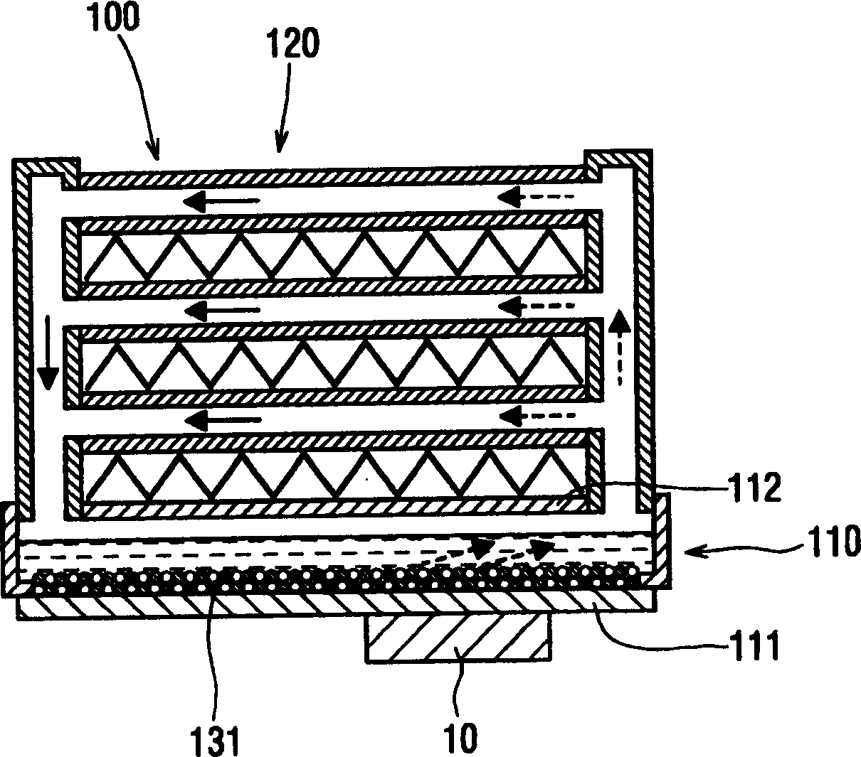
[0025] figure 1 , figure 2 The first embodiment of the ebullient cooling device 100 of the present invention is shown. figure 1 It is a cross-sectional view showing the ebullient cooling device 100 when the refrigerant tank 110 is positioned in the vertical direction (hereinafter referred to as "vertical direction"), figure 2 It is a sectional view showing the ebullient cooling device 100 when the refrigerant tank 110 is positioned in the horizontal direction.
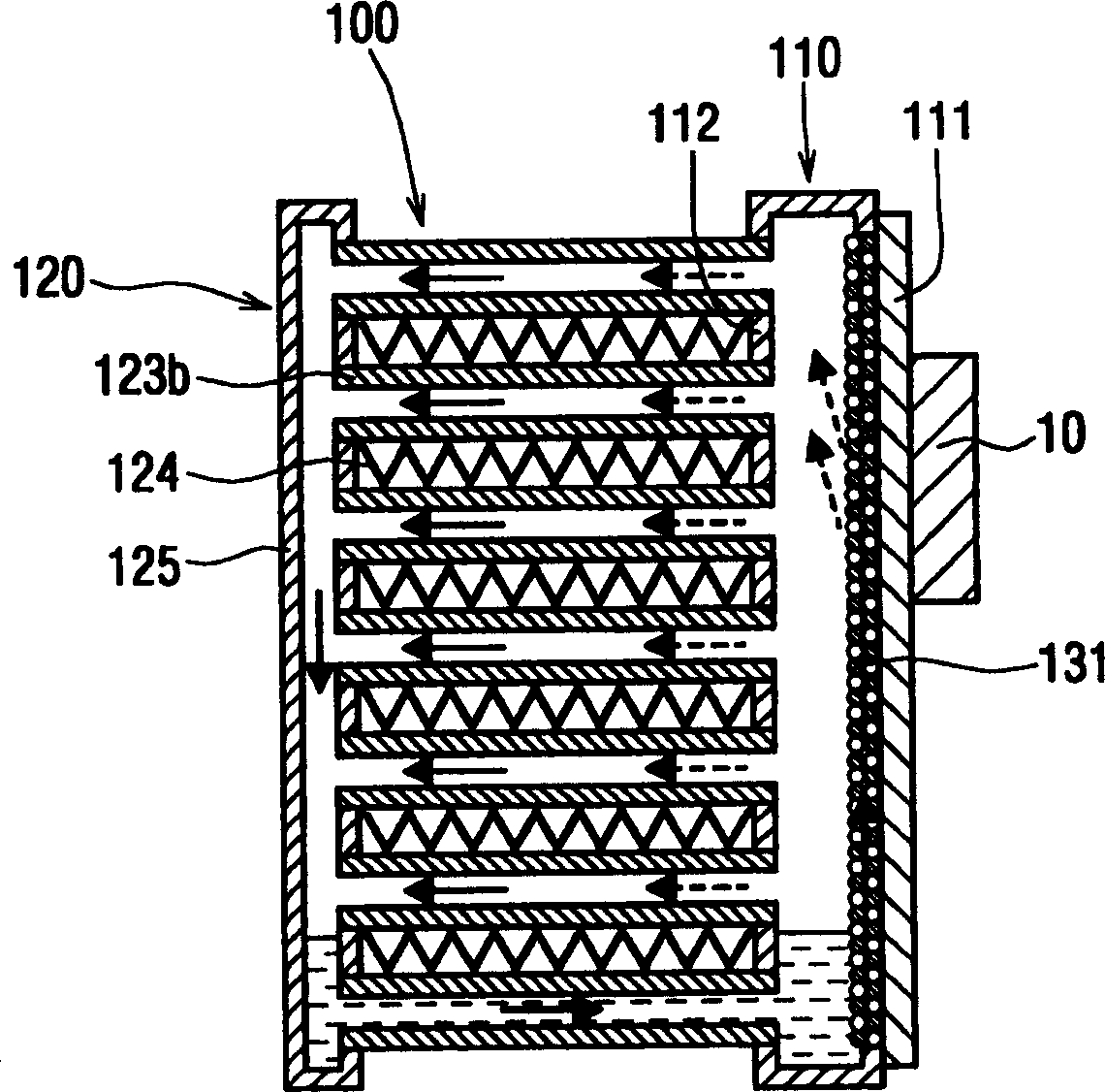
[0026] The ebullient cooling device 100 is a device for cooling a heat generating body 10 such as a semiconductor element, and is composed of a refrigerant tank 110 and a heat dissipation unit 120 . In addition, each member described below is made of a copper material or a copper-based material, and the members are integrally brazed with a brazing material applied to the joint.
[0027] First, the refrigerant tank 110 is a flat container, and has a heat receiving wall (corresponding to one wall in the present inve...
no. 2 Embodiment approach
[0041] The second embodiment of the present invention is as Figure 4 , Figure 5 shown. In the second embodiment, an oil wick (corresponding to the second oil wick of the present invention) 132 is added to the first embodiment described above.
[0042] Such as Figure 4 As shown, the oil wick 132 is arranged in the lower area of the refrigerant tank 110 when the two wall portions 111 and 112 are used in a vertical orientation. In addition, the oil wick 132 has a thicker porous structure (the formed pores are larger) than the oil wick 131 .
[0043] The ebullient cooling device 100 promotes the boiling of the refrigerant due to the heat generated by the heat generating element 10 and increases the circulation amount of the refrigerant. Then, the circulation resistance of the refrigerant in the heat radiation pipe 123a increases (the pressure loss of the refrigerant increases), as Figure 5 As shown, relative to the pressure PA at point A in the refrigerant tank 110 , th...
no. 3 Embodiment approach
[0049] The third embodiment of the present invention is as Figure 8 shown. In the third embodiment, the height difference h of the refrigerant liquid is reduced by the partition wall 113 compared to the above-mentioned second embodiment.
[0050] Partition wall 113 is arranged in an area above the refrigerant liquid surface in refrigerant tank 110 when the two wall portions 111 and 112 are used in a vertical orientation, penetrates oil wick 131 , and partitions the interior of refrigerant tank 110 to the upper side. and underside.
[0051] Therefore, the pressure PA of the boiling refrigerant in the refrigerant tank 110 does not act on the liquid refrigerant in the refrigerant tank 110, and the rise of the liquid level of the refrigerant in the heat dissipation part 120 (radiation pipe 123a) can be prevented, so that the heat dissipation part 120 can be enlarged. Condensation area for improved cooling performance.
PUM
 Abstract
Description
Claims
Application Information
 - R&D
- Intellectual Property
- Life Sciences
- Materials
- Tech Scout
- Unparalleled Data Quality
- Higher Quality Content
- 60% Fewer Hallucinations
Browse by: Latest US Patents, China's latest patents, Technical Efficacy Thesaurus, Application Domain, Technology Topic, Popular Technical Reports.
© 2025 PatSnap. All rights reserved.Legal|Privacy policy|Modern Slavery Act Transparency Statement|Sitemap|About US| Contact US: help@patsnap.com


