
Apparatus and method for forming a forward link transmission beam of a smart antenna in a mobile communication system

A technology for transmitting beams and forward links, applied in the field of smart antenna devices

Inactive Publication Date: 2005-08-10
SAMSUNG ELECTRONICS CO LTD
View PDF1 Cites 0 Cited by
  • Summary
  • Abstract
  • Description
  • Claims
  • Application Information

AI Technical Summary

Problems solved by technology

Conversely, if the bandwidth of the transmit beam is reduced in order to minimize interference, the phase mismatch increases

Method used


Image

  • Apparatus and method for forming a forward link transmission beam of a smart antenna in a mobile communication system
  • Apparatus and method for forming a forward link transmission beam of a smart antenna in a mobile communication system
  • Apparatus and method for forming a forward link transmission beam of a smart antenna in a mobile communication system

Examples


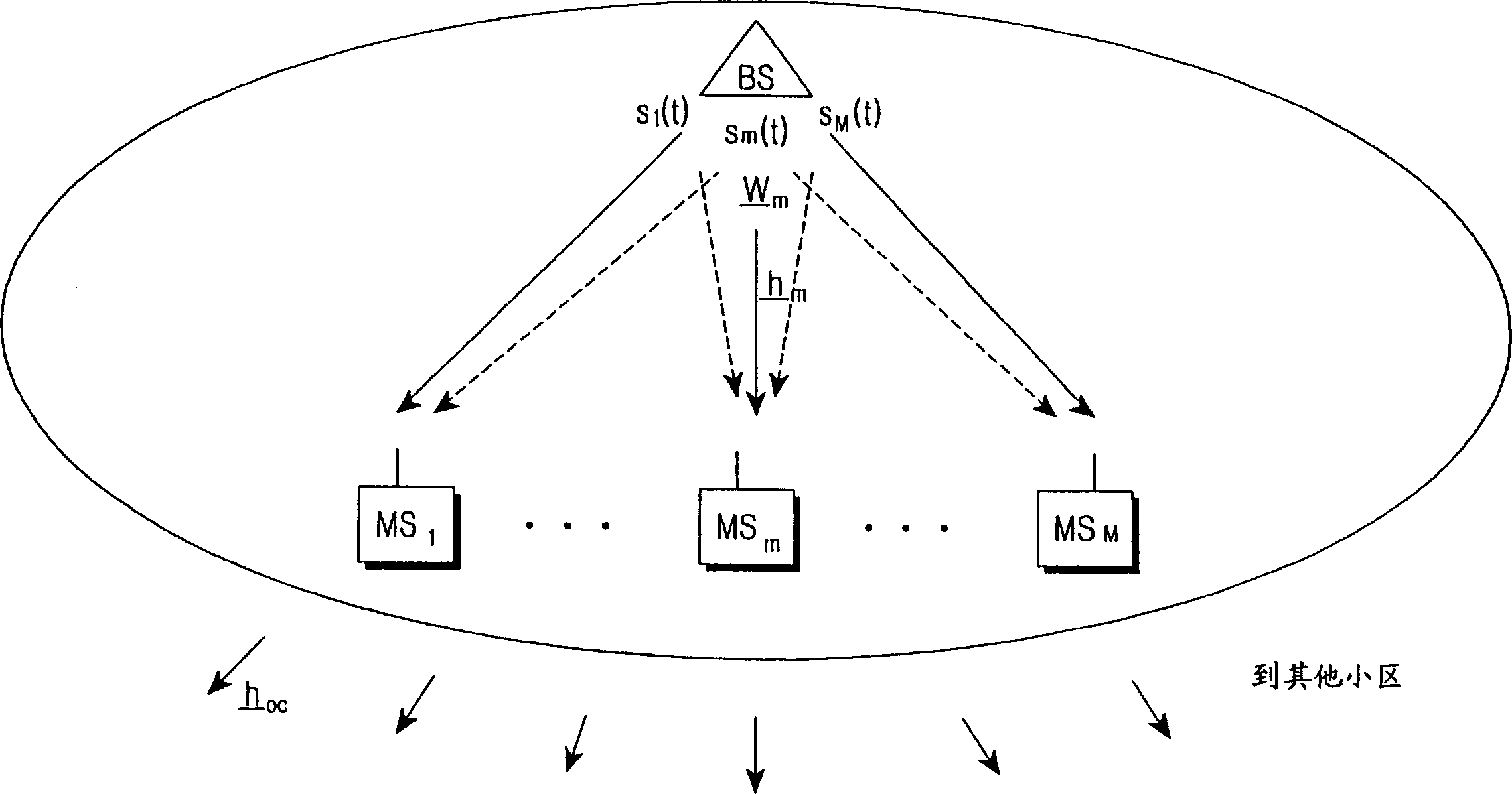
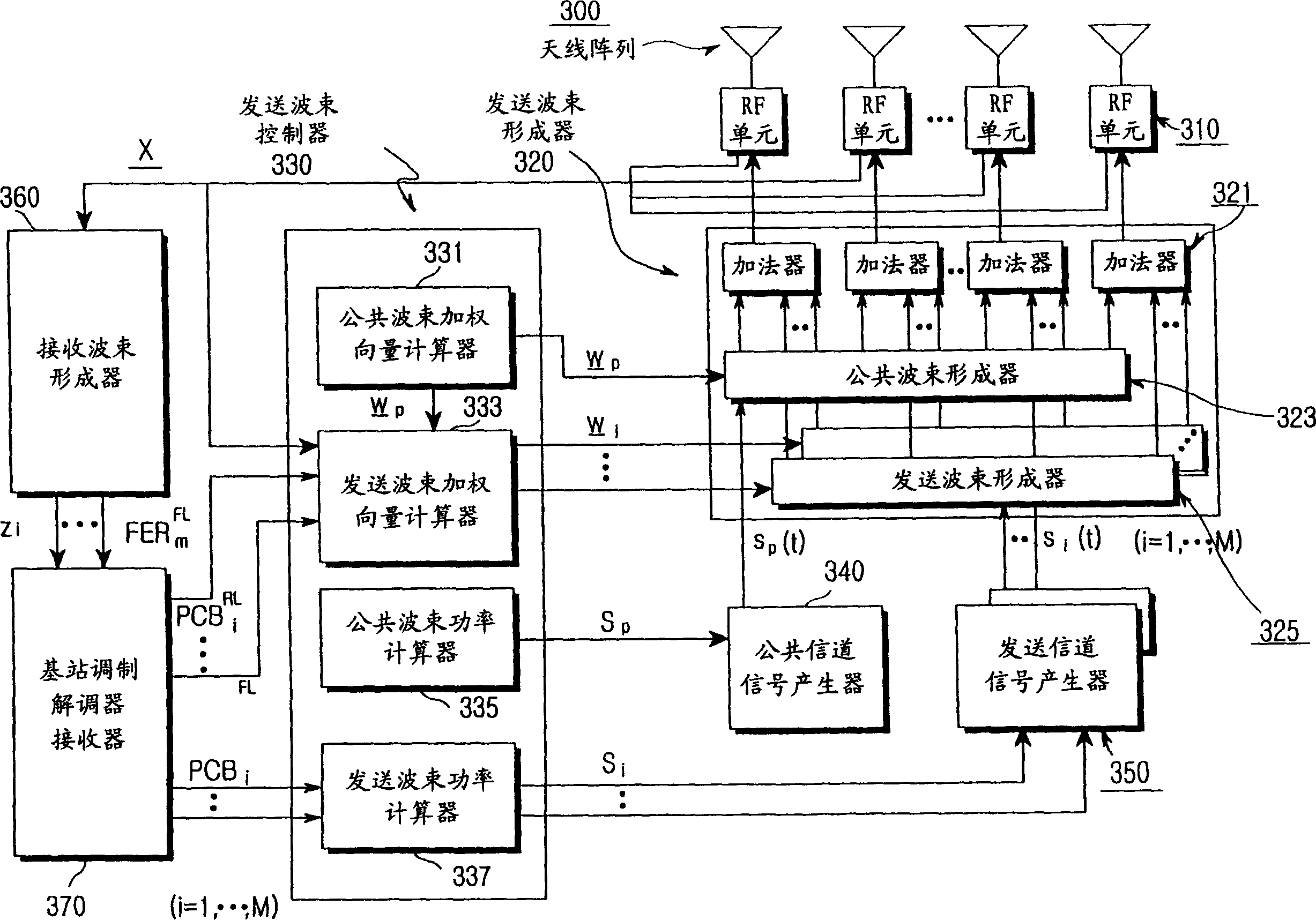
Embodiment Construction

[0027] Several embodiments of the present invention will now be described in detail with reference to the accompanying drawings. In the drawings, the same or similar elements are denoted by the same reference numerals. In the following description, a detailed description of known functions and configurations incorporated herein has been omitted for conciseness.

[0028]Embodiments of the invention are described for two different situations. The first case provides a method for computing the optimal transmit weight vector when there is no dedicated pilot channel and only common pilot channels exist. The second case provides a method for calculating the optimal transmit weight vector when a dedicated pilot channel is present, such as the special case described in connection with the prior art. Embodiments of the present invention can be generally applied to current mobile communication systems such as FDMA, TDMA and CDMA. However, for convenience, an embodiment of the present...


PUM


Abstract

A base station apparatus including an antenna array calculates a direction of a weight vector of a transmission beam so as to maximize in-phase component power for a common channel signal in a transmission channel signal for transmission to a mobile station and to minimize the sum of quadrature-phase power component and interference power for other mobile stations inside and outside a cell due to a transmission channel signal for the mobile station.

Description

technical field [0001] The present invention generally relates to a smart antenna device and method, in particular to a device and method for forming a forward link transmission beam of a smart antenna in a mobile communication system. Background technique [0002] In order to meet the rapidly increasing needs of mobile communications and provide various multimedia services to users, there is a great need to increase the capacity of the forward link. Generally, Wide Frequency Division Multiple Access (FDMA) and Time Division Multiple Access (TDMA) are used to guarantee as large a user capacity as possible with a limited available frequency band. In FDMA technology, a given frequency bandwidth is divided into multiple channels required for communication, so that each user uses a unique channel. However, in TDMA technology, each user only uses a single frequency channel during the predetermined time slots assigned to it. Also, Code Division Multiple Access (CDMA) has been pr...

Claims


Application Information

Patent Timeline
Patent Type & Authority Applications(China)
IPC IPC(8): H04B7/10G01S3/74H04B1/00H04B7/02H04B7/06H04B7/26H04W16/28
CPCG01S3/74H04W16/28H04B7/0617
Inventor 千炳珍
Owner SAMSUNG ELECTRONICS CO LTD
Learn More