
Function liquid supply apparatus, imaging apparatus, method of manufacturing electro-optical device, electro-optical device, and electronic device

A technology of electro-optical device and supply device, applied in optics, identification device, nonlinear optics, etc., can solve the problems of increased air volume and increased loss of functional fluid supply pressure and flow path, etc.

Inactive Publication Date: 2005-07-13
SEIKO EPSON CORP
View PDF1 Cites 3 Cited by
  • Summary
  • Abstract
  • Description
  • Claims
  • Application Information

AI Technical Summary

Problems solved by technology

However, when the functional liquid tank is arranged outside the moving range of the functional liquid droplet discharge head, since the functional liquid flow path from the functional liquid tank to the functional liquid droplet discharge head becomes longer, it passes through the functional liquid pipe forming the functional liquid flow path. However, the amount of air dissolved in the functional liquid in the liquid delivery in the functional liquid flow path will increase.
In addition, when the functional liquid channel becomes longer, since the amount of functional liquid remaining in the channel increases, the amount of wasted functional liquid increases, and there is also a problem that the channel loss of the functional liquid supply pressure increases.

Method used


Image

  • Function liquid supply apparatus, imaging apparatus, method of manufacturing electro-optical device, electro-optical device, and electronic device
  • Function liquid supply apparatus, imaging apparatus, method of manufacturing electro-optical device, electro-optical device, and electronic device
  • Function liquid supply apparatus, imaging apparatus, method of manufacturing electro-optical device, electro-optical device, and electronic device

Examples


Embodiment Construction

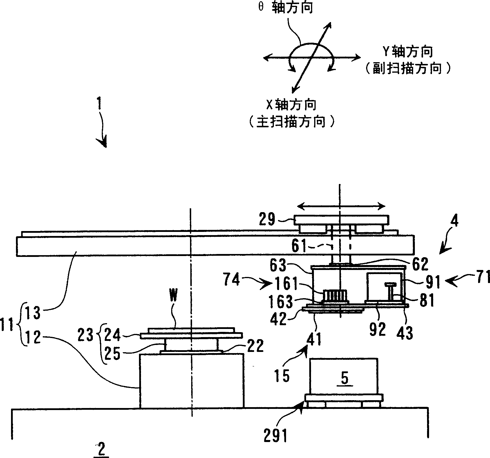
[0062] A drawing device to which the present invention is applied will be described below with reference to the drawings. This drawing device is installed in the production line of the so-called flat panel display, and it is used to form the color filter of the liquid crystal display device or each pixel constituting the organic EL device by the droplet discharge method using the functional droplet discharge head. Devices such as light emitting elements.

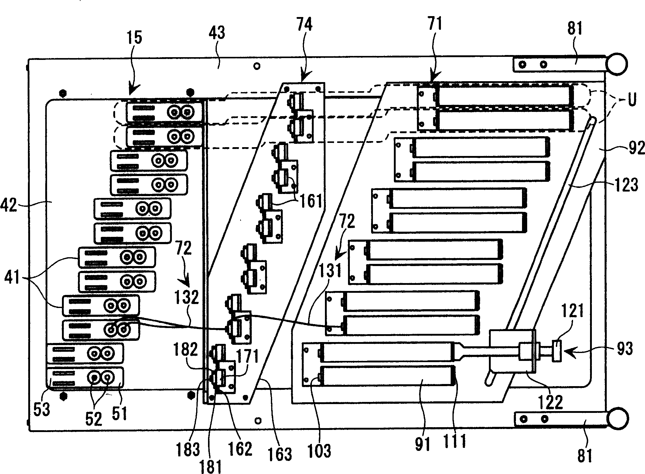
[0063] Such as figure 1 and figure 2 As shown, the drawing device 1 has: a machine 2, a droplet ejection device 3 having a functional droplet ejection head 41 and being placed on the entire area of ​​the machine 2, and a function connected to the droplet ejection device 3 The liquid supply device 4 and the nozzle maintenance device 5 placed on the machine platform 2 in a manner attached to the droplet ejection device 3 . In addition, on the drawing device 1, a control device 6 not shown in the figure is provided. In the ...


PUM


Abstract

The present invention provides a functional liquid supply device, which is a functional liquid supply device (4) for supplying functional liquid to a functional liquid drop nozzle (41) mounted on a carriage (63), comprising: a functional liquid tank (91); The functional liquid introduced into the primary chamber (172) from the functional liquid tank (91) is supplied to the functional droplet discharge head (41) through the secondary chamber (173), and one surface constituting the secondary chamber (173) is directed to the atmosphere. The atmospheric pressure received by the circular diaphragm (175) is used as the reference adjustment pressure, and the pressure adjustment valve (161) that opens and closes the communication flow path connecting the primary chamber (172) and the secondary chamber (173); Adjust the valve (161) to connect the connecting pipe (72) of the functional liquid tank (91) and the functional liquid drop nozzle (41), wherein the functional liquid tank (41) and the pressure regulating valve (161) are mounted on the carriage (63) superior. As a result, the freedom of installation of the functional liquid tank (91) can be ensured, and the functional liquid flow path can be shortened.

Description

technical field [0001] The present invention relates to a functional liquid supply device for supplying a functional liquid to a functional liquid drop discharge head mounted on a carriage, a drawing device, a method for manufacturing an electro-optical device, an electro-optical device, and an electronic device. Background technique [0002] In an inkjet printer which is one type of drawing device, in order to prevent dripping of ink (functional liquid) from an inkjet head (functional liquid droplet ejection head) and ensure the amount of ink droplets ejected from the inkjet head To achieve the stability of the inkjet head, the ink cartridge (functional liquid tank) that supplies ink to the inkjet head is arranged at a lower position than the inkjet head (nozzle surface) to achieve a predetermined water head difference. In addition, printing (drawing) is performed on a printing object by ejecting the inkjet head while relatively moving the printing object (work) with respec...

Claims


Application Information

Patent Timeline
Patent Type & Authority Applications(China)
IPC IPC(8): B41J2/175G02B5/20G02F1/1335G09F9/00
CPCB41J2/175B41J2/17509B41J2/17523B41J2/17596
Inventor 林高之小野健一
Owner SEIKO EPSON CORP
Learn More