
Intervertebral prosthesis especially for a neck vertebral support

A kind of intervertebral disc, artificial technology, applied in the direction of medical science, spinal implants, prosthesis, etc., can solve the problem of no or incomplete arrival of braking components

Inactive Publication Date: 2005-06-01
CERVITECH INC
View PDF4 Cites 10 Cited by
  • Summary
  • Abstract
  • Description
  • Claims
  • Application Information

AI Technical Summary

Problems solved by technology

For occasional reasons not visible to the operator, it may happen that the detent element does not or does not fully reach the locking position, for example due to objects in the locking groove or the artificial nucleus pulposus cannot be fully pushed into the base due to accidental obstructions

Method used


Image

  • Intervertebral prosthesis especially for a neck vertebral support
  • Intervertebral prosthesis especially for a neck vertebral support
  • Intervertebral prosthesis especially for a neck vertebral support

Examples


Embodiment Construction

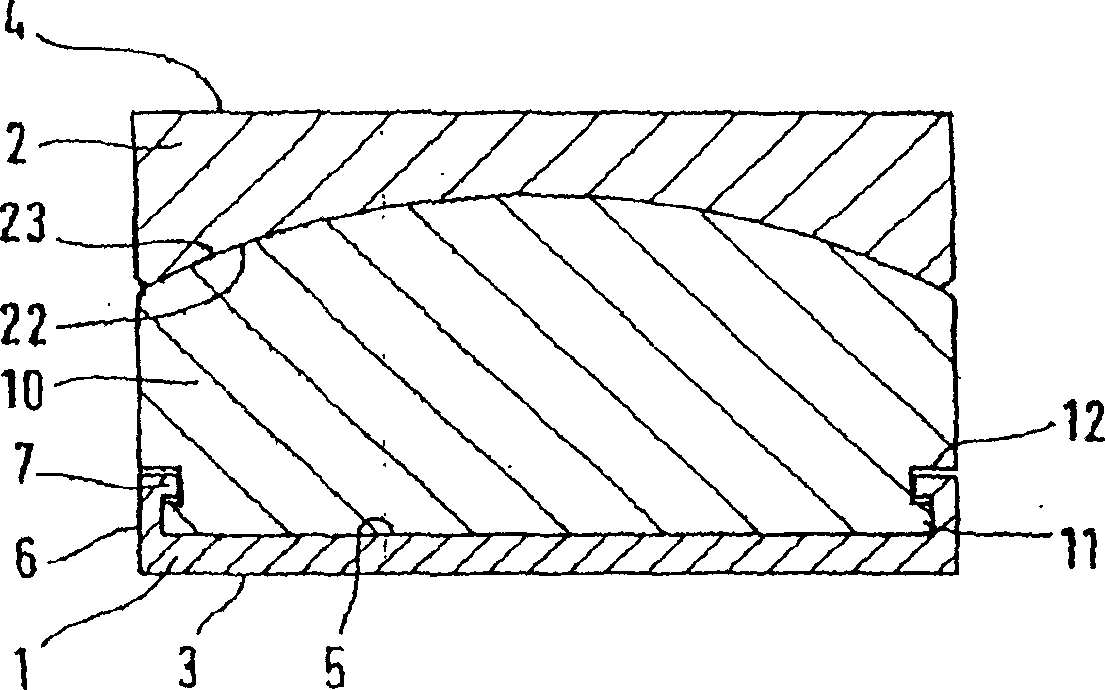
[0030] The lower cover plate 1 and the upper cover plate 2 of the first embodiment have an outer surface 3 or 4, which stipulates that it is fixed to the associated vertebral body. The outer surface is preferably flat. However, other substantially planar surface shapes are also conceivable, as long as they facilitate a good fixation on the vertebrae. The cover is preferably made of metal.

[0031] The one side of lower cover plate 1 facing upper cover plate 2 is a flat bottom surface 5, and its three sides are collar 6 shape borders, constitute inwardly protruding frame 7 in the collar interior otch top. The top view of the lower cover plate 1 is egg-shaped or approximately rectangular.

[0032] The bottom surface 5 and the collar 6 of the lower cover plate 1 form a base for the artificial nucleus pulposus 10, and the artificial nucleus pulposus is made of a material that facilitates sliding, such as polyethylene. The artificial nucleus pulposus has a lower plane matched wi...


PUM


Abstract

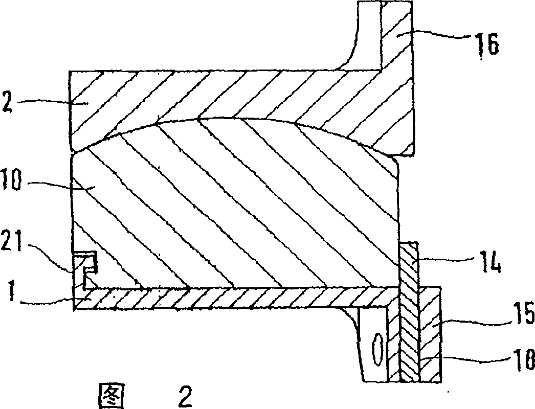
The invention relates to an intravertebral prosthesis, in particular for the cervical vertebral column, essentially comprising a first cover plate (1), for connection to a first vertebral body, a second cover plate (2), for connection to a second vertebral body and a prosthesis centre (10), which forms a joint with the second cover plate (2). The prosthesis centre (10) is held by a seat (9, 5) in the first cover plate (1), embodied as a guide device (7, 11, 12). The centre (10) may be inserted into the guide device from the ventral side in the AP direction (A) relative to the first cover plate (1). A stop plate (14) is provided on the ventral edge of the first cover plate which may be displaced in a sliding guide (18), between a locking and a non-locking position.

Description

technical field [0001] Artificial discs are used to replace spinal discs. The artificial intervertebral disc is composed of two cover plates and a joint device, the outer surfaces of the two cover plates are used to connect adjacent vertebral bodies, and the joint device is located between the two cover plates. The inner edge of the upper plate of the known artificial intervertebral disc (WO 01 / 01893, FR-A-2718635) is a concave spherical articular surface, which forms a joint with the convex spherical surface on the artificial nucleus pulposus made of polyethylene. The flat bottom surface and edges of the artificial nucleus rest in a suitable base which is part of the lower cover plate. The base is composed of a flat bottom surface and raised edges on three sides (both sides and the back side). The two edges in the AP direction are basically concave frames, which complementarily match with the protruding frames and grooves of the artificial nucleus pulposus. The ventral end...

Claims


Application Information

Patent Timeline
Patent Type & Authority Applications(China)
IPC IPC(8): A61F2/00A61F2/30A61F2/44
CPCA61F2/4425A61F2002/30387A61F2002/30392A61F2002/30397A61F2002/304A61F2002/30517A61F2002/30571A61F2002/30578A61F2002/30616A61F2002/30649A61F2002/3065A61F2002/443A61F2220/0025A61F2310/00011
Inventor A·凯勒P·C·麦卡菲
Owner CERVITECH INC
Learn More