Eureka AIR delivers breakthrough ideas for toughest innovation challenges, trusted by R&D personnel around the world.

Cathode-ray tube hopper package

A cathode ray tube and packaging technology, applied in the direction of cathode ray/electron beam tube shell/container, type of packaging items, special packaging items, etc., can solve problems such as weak support rigidity

Inactive Publication Date: 2005-03-23
郑志源 +1
View PDF0 Cites 1 Cited by
  • Summary
  • Abstract
  • Description
  • Claims
  • Application Information

AI Technical Summary

Problems solved by technology

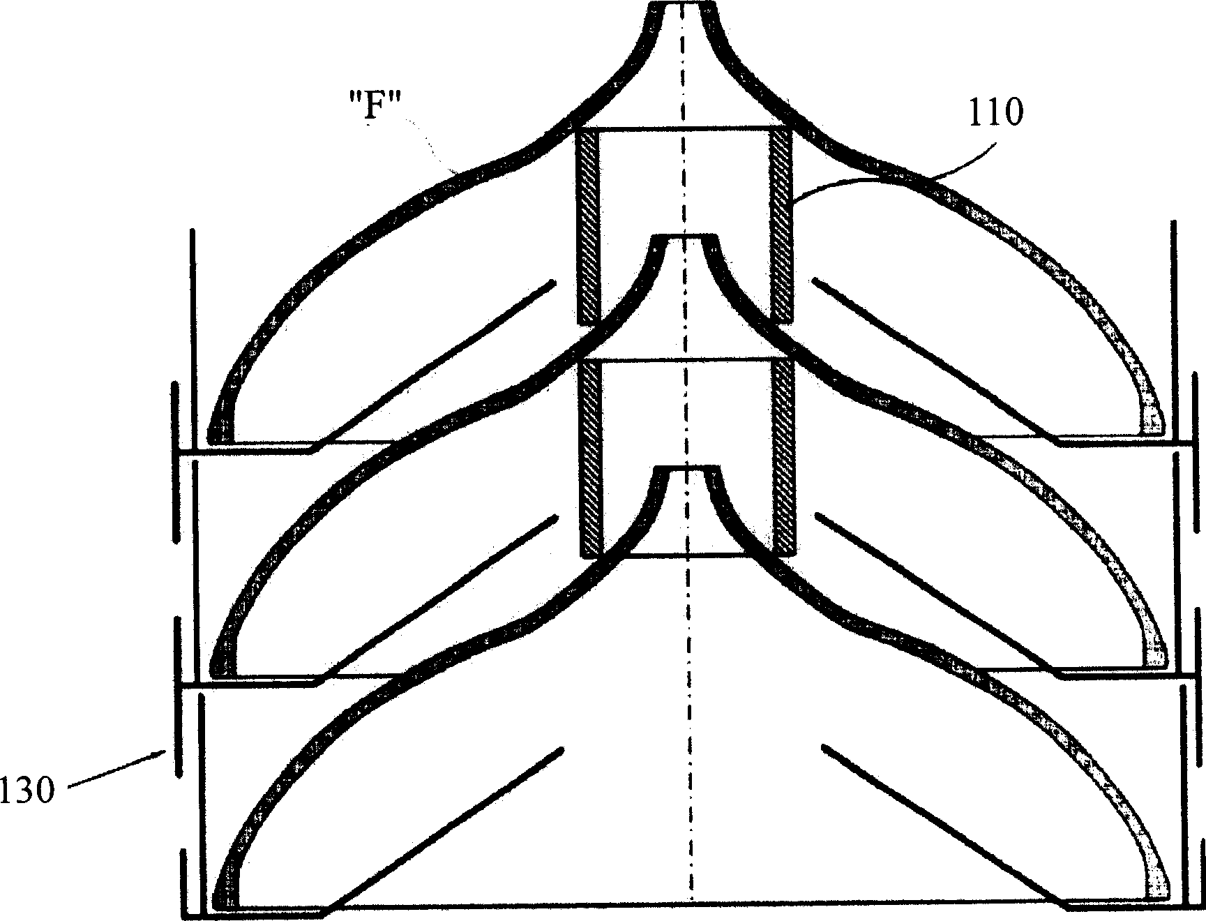
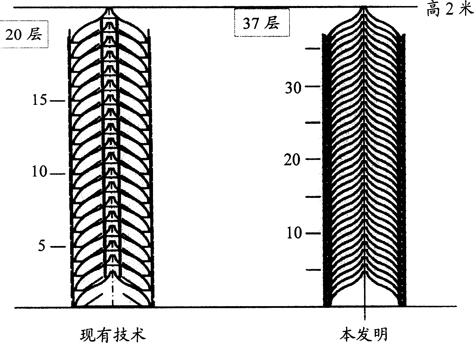
[0012] Moreover, since the existing funnel wrapper 130 is made of paper, its material characteristics determine that the support rigidity in the vertical direction will be weak.

Method used


Image

  • Cathode-ray tube hopper package
  • Cathode-ray tube hopper package
  • Cathode-ray tube hopper package

Examples


no. 1 example

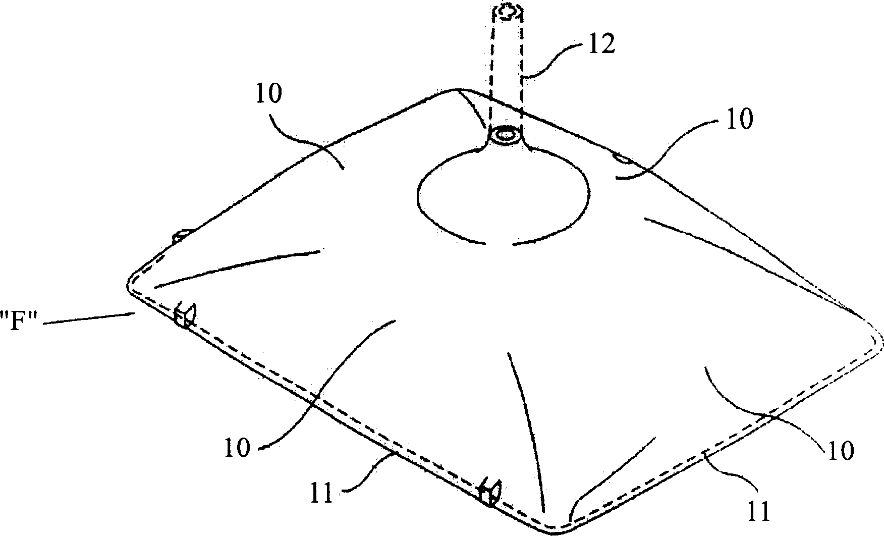
[0046] Figure 3a and Figure 3b Schematic diagrams of the front and back of the funnel, respectively. As shown in the figure, the funnel F, which is a part of a cathode ray tube (CRT), is a funnel-shaped glass product connected to the rear of a panel (Panel, not shown).

[0047] The funnel F almost all forms a quadrilateral, including a flat bottom surface 11 at the end and a funnel-shaped inclined surface 10 bent from each side of the bottom surface 11 toward the center. An anode cap (Anode Button) not marked with reference numerals is attached to the ramp 10 . The central area of ​​the bevel 10 will join with the electron gun neck 12 (Neck) indicated by the dotted line in the figure. As mentioned above, the packages 30 , 31 , 32 , , , are used to package the funnel F excluding the electron gun neck 12 .

[0048] Figure 4a and Figure 4b The front and back schematic diagrams of the cathode ray tube funnel package according to the first embodiment of the present invent...

no. 2 example

[0073] Figure 9a and Figure 9b The placement states of the cathode ray tube funnel packages according to the second embodiment of the present invention are shown respectively.

[0074] The pallet used to support the goods in the general container ( Figure 8 The size of the lower wood part) is constant. Therefore, on this pallet as a benchmark, stack the packages 40-43 on a pallet and pack the funnel F. In order to make the packages 40-43 mutually detachable, a design is also made on the side wall 1. Has a concave-convex snap-fit ​​structure.

[0075] refer to Figure 9a One of the packages 40 has a concave-convex fastening structure on four sides, and its shape can be any one of the convex parts 51a, 51b, and the concave parts 52a, 52b.

[0076] The sidewalls 1 of the packages 40-43 are designed with alternately arranged convex parts 51a, 51b and concave parts 52a, 52b, so that the adjacent packages can be linked horizontally, so that they can be packaged in 4 packages...


PUM


Abstract

The packaging material is provided with a bottom part to support the bottom face of the funnel, a side wall part 1 which is bent upward from the outer end of the bottom part to form a side wall, at least a pair of stacking-connection projections which are extended upward along the side wall part from the bottom part in order to detachably connect adjacent packaging materials and a contact prevention part which is extended aslant along the slop surface of the funnel from the inner end of the bottom part in order to prevent the stacked funnels from coming in contact with each other and has an opening to partially expose the funnel formed at the center part. In this way, it can provide a packaging material for a funnel for a cathode-ray tube, with which the funnel can be loaded easily in the height direction while the height between layers is decreased as much as possible so that more funnel can be loaded per unit height and the supporting rigidity in the height direction of which is increased so that the funnel can be loaded vertically without an inclination.

Description

technical field [0001] The present invention relates to a cathode ray tube funnel package, more specifically, the package conveniently stacks the funnels vertically while minimizing the layer spacing, thereby increasing the number of stackable funnels per unit height, and because the funnels along the vertical There is strong supporting rigidity in the vertical direction, so that the stacked body is straight. Background technique [0002] A cathode ray tube (CRT) is a type of glass used in a television or computer monitor. The cathode ray tube is composed of a panel (Panel) placed in front for projecting images, a funnel (Funnel) connected to the rear of the panel, and an electron gun neck (Neck) at the end of the funnel for installing an electron gun. [0003] The panels and funnels are made of molten glass called glass gobs, which are pressurized and formed, and then certain parts are ground and inspected to make semi-finished products. After the semi-finished products a...

Claims


Application Information

Patent Timeline
Patent Type & Authority Applications(China)
IPC IPC(8): B65D21/02B65D1/34B65D57/00B65D85/42B65D85/48
CPCB65D21/0204B65D21/0233B65D85/42H01J2229/8603
Inventor 郑志源
Owner 郑志源
Why Eureka
Eureka Blog
Learn More