
LCD device and method of driving LCD panel

A technology of liquid crystal display and equipment, applied in the field of liquid crystal display equipment

Active Publication Date: 2004-10-27
HANNSTAR DISPLAY CORPORATION
View PDF1 Cites 8 Cited by
  • Summary
  • Abstract
  • Description
  • Claims
  • Application Information

AI Technical Summary

Problems solved by technology

The invention solves the problem of different shades of gray across the screen of a liquid crystal display since the pulse duration can be easily controlled by a digital circuit

Method used


Image

  • LCD device and method of driving LCD panel
  • LCD device and method of driving LCD panel
  • LCD device and method of driving LCD panel

Examples


Embodiment Construction

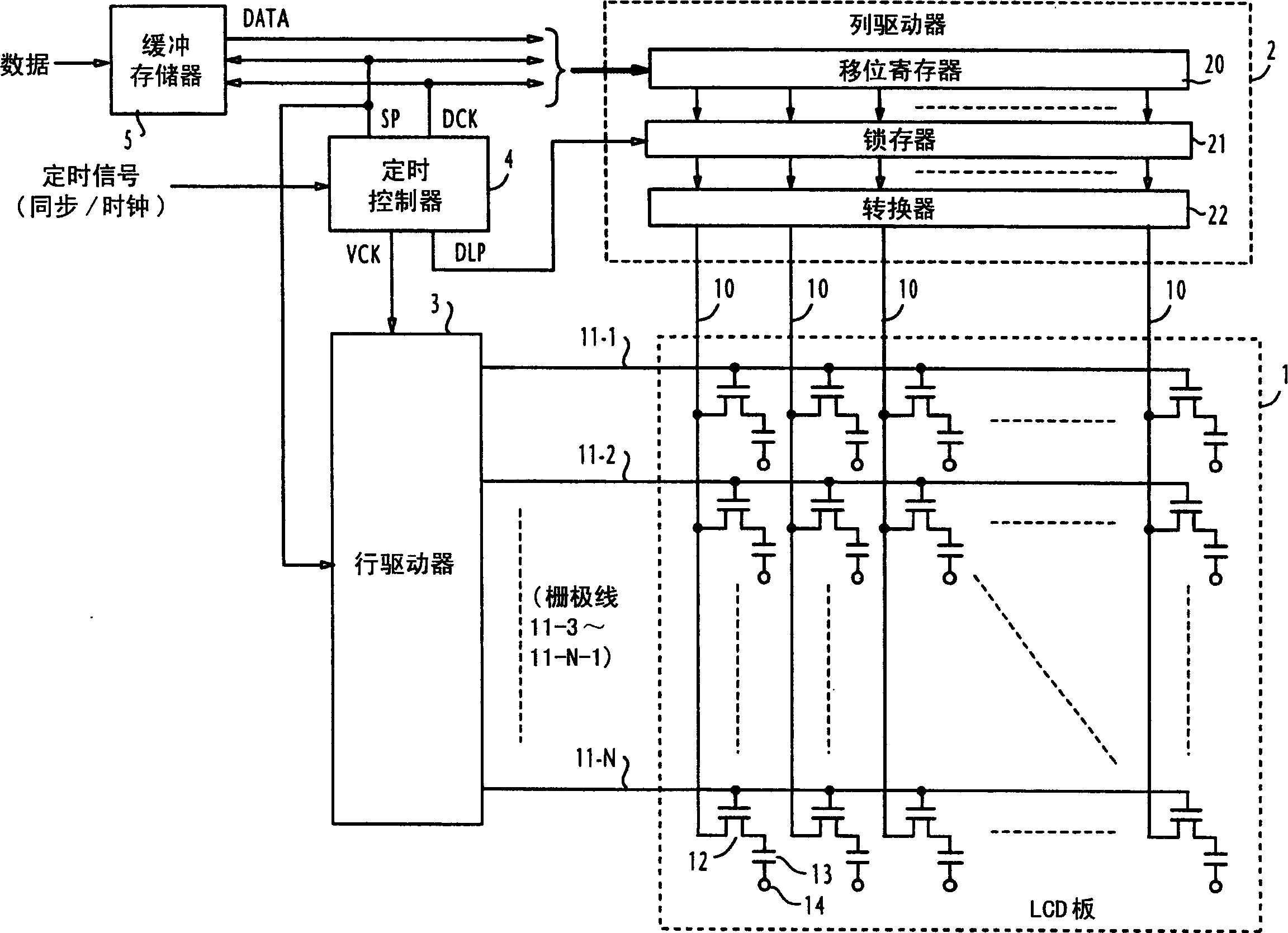
[0022] Now, refer to figure 2 , which shows an LCD driving circuit according to a first embodiment of the present invention. The drive circuit includes a column driver 2 and a row driver 3 for respectively driving the liquid crystal display panel 1 in response to timing pulses supplied from a timing controller 4 . In a first embodiment, the vertical blanking interval of each frame is used to stretch the gate control pulse longer than the usual gate on time. For this purpose, a buffer memory is provided for temporarily storing video input data from an external source not shown. The stored video data is supplied to the column driver 2 line by line. Input timing signals (sync and clock) are also provided to the timing controller 4 from external sources.

[0023] The LCD panel 1 includes a plurality of column (drain) lines 10 connected to the column driver 2 for receiving video signals; and a plurality of horizontal row (gate) lines 11-1 to 11-N connected to the row driver 3, ...


PUM


Abstract

In a liquid crystal display apparatus, a set of write-in voltages are generated corresponding to a horizontal line signal of an input video frame so that they appear at end points of the column lines of a LCD panel. The row lines of the LCD panel are successively selected and the write-in voltages are supplied from the end points of the column lines to the liquid crystal cells of the selected row line for a variable write-in period. In order to compensate for shades-of-gray differences between the top and bottom of the LCD panel, the write-in period is increasingly varied as a function of the geometric distance from the selected row line to the end points of the column lines. The write-in period may be increasingly variable from a nominal value, or from a less-than-nominal value to the nominal value, or a combination of both.

Description

technical field [0001] The invention relates to a liquid crystal display device and a method for driving a liquid crystal display panel. Background technique [0002] A liquid crystal display panel includes a matrix array of pixels, where each pixel is formed by a switching transistor and a liquid crystal cell. All switching transistors are connected to the intersections of successively selected column and row lines. When a row line is selected, the column lines are respectively driven by the write voltage. With the advancement of technology in the field of flat panel displays, the current trend is toward large-scale, high-definition display panels. As screen size increases, write voltages must cross column lines of increasing length. Since the write voltage is supplied to the liquid crystal cells of the selected row line during a fixed write period, these liquid crystal cells suffer from undesirable attenuation and distortion, such as figure 1 As shown, this causes diff...

Claims


Application Information

Patent Timeline
Patent Type & Authority Applications(China)
IPC IPC(8): G02F1/133G09G3/20G09G3/36
CPCG09G3/3648G09G2320/0223G09G2310/02F24F6/12F24F2221/12Y02B30/70
Inventor 武田广山口真智彦
Owner HANNSTAR DISPLAY CORPORATION
Learn More