
Tail-gas purification system and method

An exhaust gas purification and exhaust gas technology, which is used in the treatment of ash accumulated on a particulate filter, the exhaust gas purification field of internal combustion engines, and can solve problems such as increasing exhaust pressure, reducing the capacity of diesel particulate filter, and reducing filter area.

Inactive Publication Date: 2004-08-04
NISSAN MOTOR CO LTD
View PDF1 Cites 32 Cited by
  • Summary
  • Abstract
  • Description
  • Claims
  • Application Information

AI Technical Summary

Problems solved by technology

Excessive ash accumulation on the DPF will not only increase the exhaust pressure but also reduce the effective filter area and thus reduce the capacity of the DPF

Method used


Image

  • Tail-gas purification system and method
  • Tail-gas purification system and method
  • Tail-gas purification system and method

Examples


Embodiment Construction

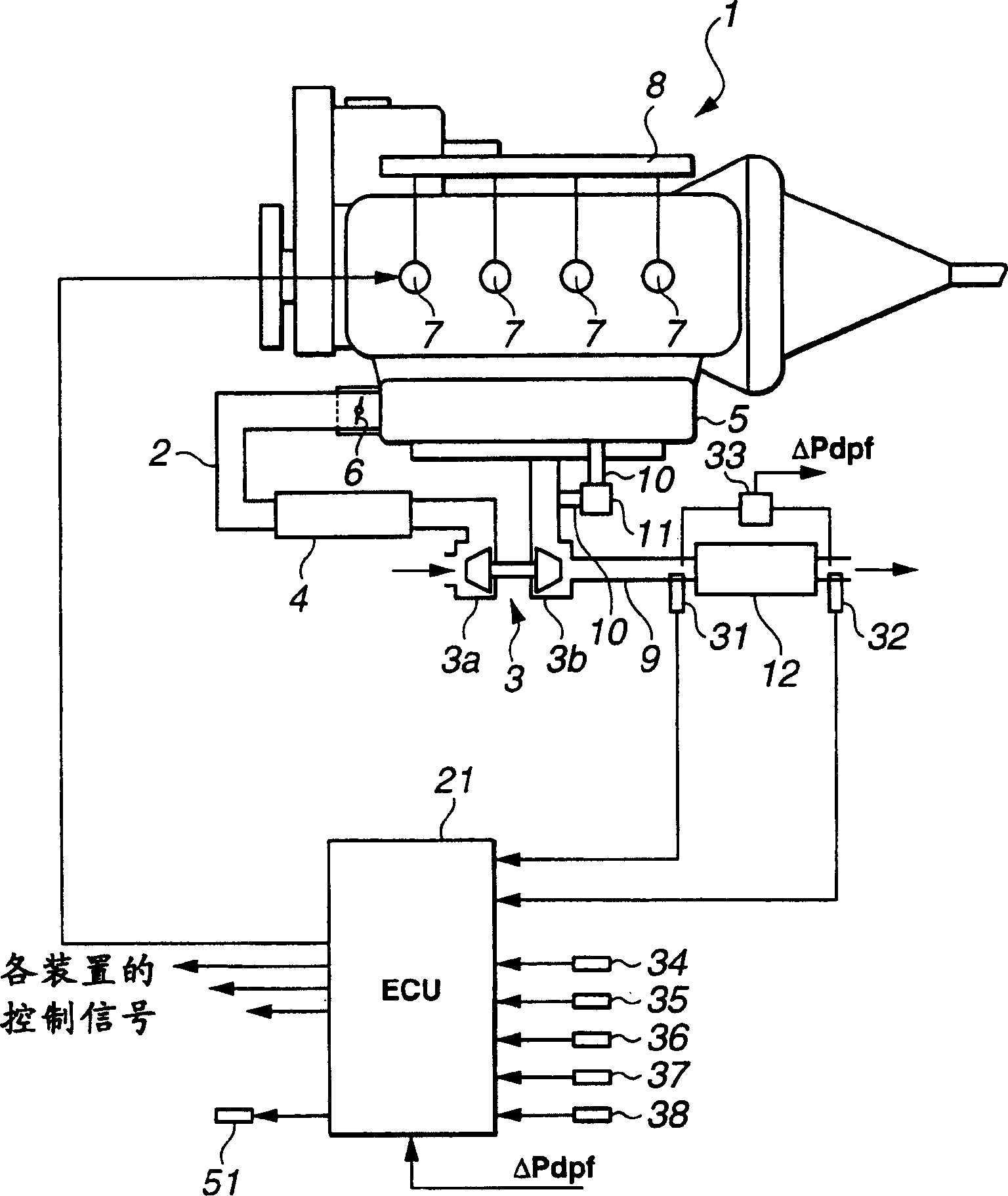
[0022] first reference figure 1 , represented by 1 direct injection diesel engine (hereinafter referred to as engine).

[0023] The engine 1 includes an intake passage 2 having an air cleaner (not shown) at an inlet portion thereof by which dust contained in intake air is removed. A compressor section 3a of a variable nozzle turbocharger (hereinafter simply referred to as a turbocharger) 3 is provided downstream of the air cleaner. The suction air passing through the air cleaner is compressed by the compressor section 3a and sent forward. Downstream of the compressor section 3a is provided an intercooler 4 by which the intake air sent forward from the compressor section 3a is cooled. In addition, a throttle valve 6 is provided immediately upstream of the buffer tank 5, so that cooled intake air flows through the throttle valve 6 into the buffer tank 5, and then is sent to each cylinder (not shown) through a manifold section (not shown). )middle.

[0024] The injectors are ...


PUM


Abstract

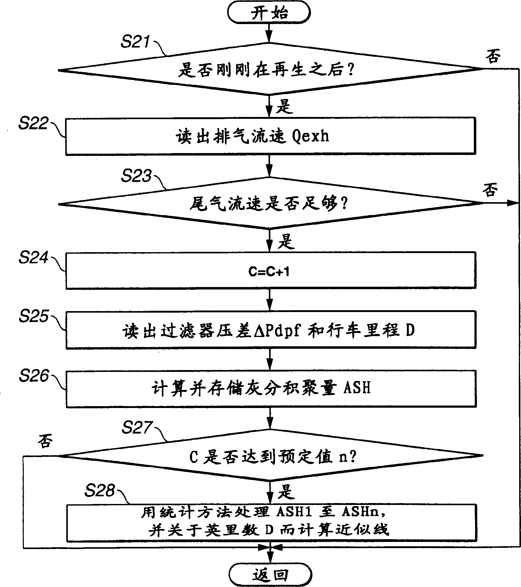
An exhaust gas purification system includes a particulate filter, a sensor that detects a filter differential pressure and a controller that controls regeneration of the particulate filter. The controller is programmed to execute a control for burning particulate accumulated on the particulate filter, determine whether regeneration of the particulate filter is completed, detect, in cooperation with the sensor, a filter differential pressure immediately after it is determined that regeneration of the particulate filter is completed, and estimate an ash accumulation amount based on the detected filter differential pressure. An exhaust gas purification method is also provided.

Description

technical field [0001] The present invention relates to an exhaust gas purification system having a particulate filter for after-treatment, mainly of exhaust gas from a diesel engine, and more particularly to a system for treating ash accumulated on the particulate filter technology. The invention also relates to a method for purifying exhaust gas of an internal combustion engine. Background technique [0002] A diesel particulate filter is a particulate trap composed of a honeycomb monolith made of ceramics or the like, and is generally used to remove particulate matter (hereinafter referred to as particulate) emitted from a diesel engine. During operation of the engine, particulates gradually accumulate on the diesel particulate filter. Sometimes, when the amount of particulates accumulated exceeds the allowable amount, it clogs the diesel particulate filter, causing the exhaust air pressure to increase, thereby adversely affecting the performance of the engine. For thi...

Claims


Application Information

Patent Timeline
Patent Type & Authority Applications(China)
IPC IPC(8): F02D45/00F01N3/02F01N3/023F01N9/00F01N11/00F02B37/00F02D41/02F02D41/22F02M25/07
CPCF02D2200/0404F02D41/187Y02T10/47F02D2200/0812F02D41/1448F02B37/00F02D41/029F02D2200/501F01N9/002F01N11/00F01N2430/00F01N3/023F02M25/0707Y10S55/30F01N2550/04F02B29/0406F02M26/05Y02T10/40
Inventor 井上尊雄川岛純一筒本直哉大竹真近藤光德古贺俊雅
Owner NISSAN MOTOR CO LTD
Learn More