Error control processing method for CD drive track-finding servo

A technology of error control and processing method, applied in the direction of optical recording/reproduction, head configuration/installation, data recording, etc., which can solve the problems of reading failure, slow data reading, poor design, etc.

Inactive Publication Date: 2004-06-30
LITE ON TECH CORP
View PDF0 Cites 1 Cited by
  • Summary
  • Abstract
  • Description
  • Claims
  • Application Information

AI Technical Summary

Problems solved by technology

like figure 2 As shown, at time point 62, the optical head track-locking action is successful, but it has taken a long time (t), and if the design of the tracking servo

Method used


Image

  • Error control processing method for CD drive track-finding servo
  • Error control processing method for CD drive track-finding servo
  • Error control processing method for CD drive track-finding servo

Examples


Embodiment Construction

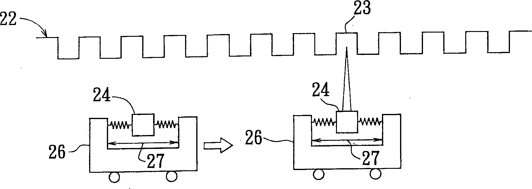
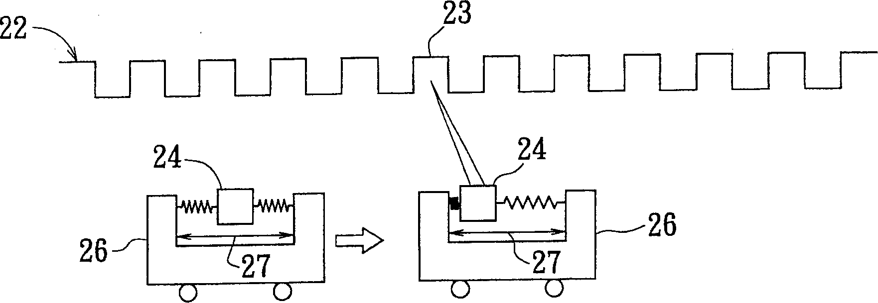
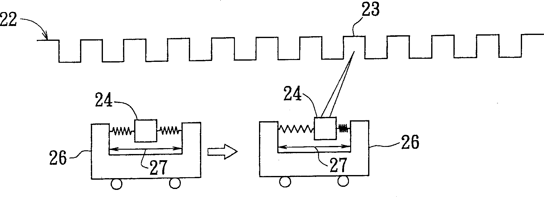
[0023] The present invention is an improvement aimed at the fact that when the track-locking action of the known optical head fails, the track-tracking servo system will take quite a long time to try to perform the track-locking action of the optical head, or there is no way to complete the track-locking action at all. The present invention starts to calculate a track-locking time when the track-locking action of the optical head starts. Generally speaking, the rail-locking action of the optical head takes a very short time, and the rail-locking action of the optical head can be completed within a few microseconds (us). When the rail locking time exceeds an expected time, it can be determined that the rail locking action fails, and according to the embodiment of the present invention, the expected time is 3 milliseconds (ms). Therefore, when the track-locking time exceeds 3 milliseconds, according to the embodiment of the present invention, the track-locking action must be aba...


PUM


Abstract

At starting action for making optical header Track On, that is at time of changing Seeking Sevo system to Tracking Sevo system to control optical header, the Track On time begins to calculate. If the Track On time exceeds a preset time, action for making optical header Track On is quit. Next, activating central servo control system or vibrating the optical header in free frequency makes the optical header move to central position within movable region. Then, another Track On action is carried out.

Description

technical field [0001] The invention relates to a tracking servo control method of an optical drive, in particular to an error control and processing method of the tracking servo of the optical drive. Background technique [0002] Optical discs are fast random access (Random Access) storage media. In order to meet this requirement, the optical drive must be able to use the Seeking Servo to accurately send the Sledge to the target position at the fastest speed at any time, and then the Tracking Servo will take over. The Track On action of the optical head. However, under the dual requirements of speed and accuracy, the optical head will inevitably have many factors such as out of focus or excessive shaking, which will cause the slider to reach the target position but cannot lock the optical head on the target track in time. [0003] For example, refer to Figure 1A , which is a schematic diagram of the known track-locking action of the trolley and the optical head. General...

Claims


Application Information

Patent Timeline
IPC IPC(8): G11B7/085G11B7/09
Inventor 徐正煜符湘益李敦介陈福祥蔡耀州
Owner LITE ON TECH CORP
Why Eureka
Try Eureka