Needle thread taking-up lever for sewing machine

A thread take-up lever and sewing machine technology, applied in the field of thread take-up levers, can solve problems such as thread hanging troubles

Inactive Publication Date: 2004-04-14
AXE YAMAZAKI
View PDF1 Cites 8 Cited by
  • Summary
  • Abstract
  • Description
  • Claims
  • Application Information

AI Technical Summary

Problems solved by technology

[0009] in addition, Figure 4 And the thread take-up lever described in any one of the patent documents 1, when hanging the thread, the suture poured from the bobbin must pass through the narrow slit extending in the up and down direction and formed on the sewing machine head, and in the slit The upper part of the seam is folded back down along the upper edge of the

Method used


Image

  • Needle thread taking-up lever for sewing machine
  • Needle thread taking-up lever for sewing machine
  • Needle thread taking-up lever for sewing machine

Examples


Embodiment Construction

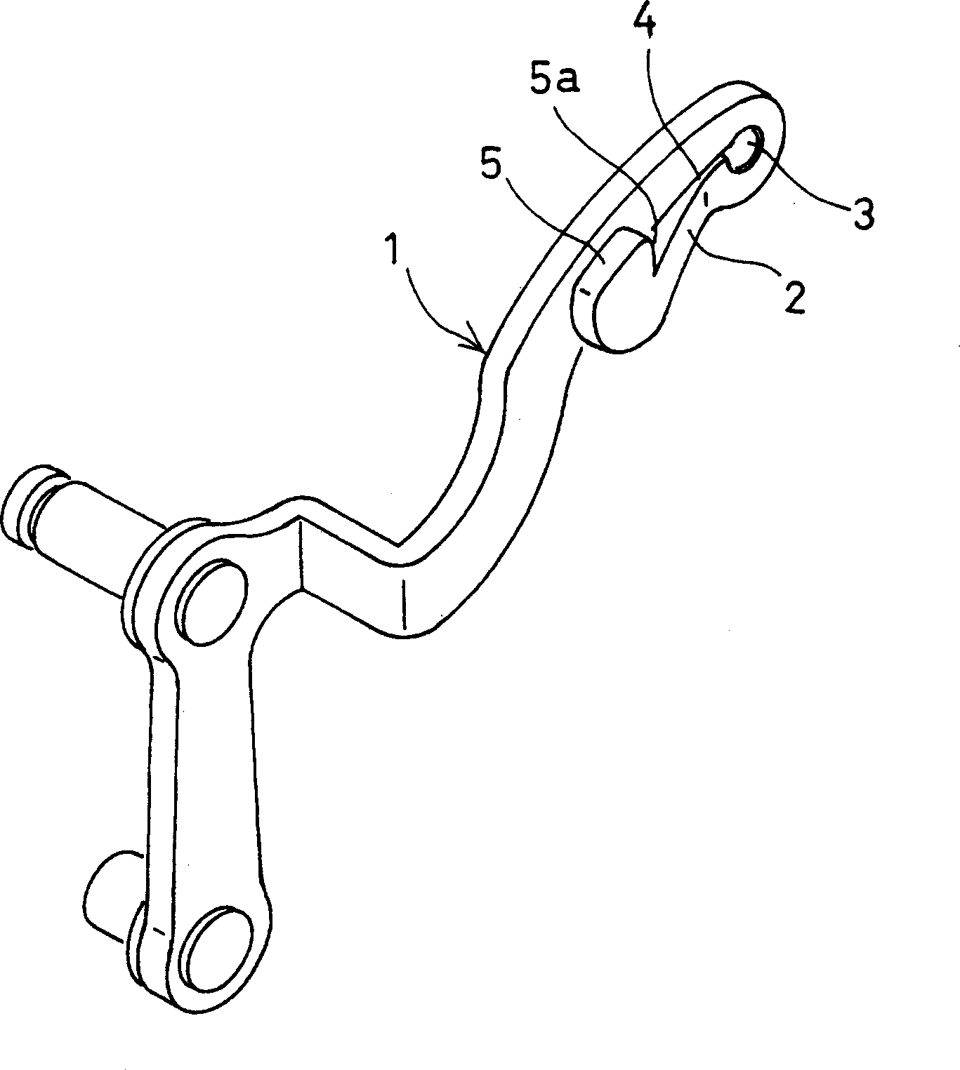
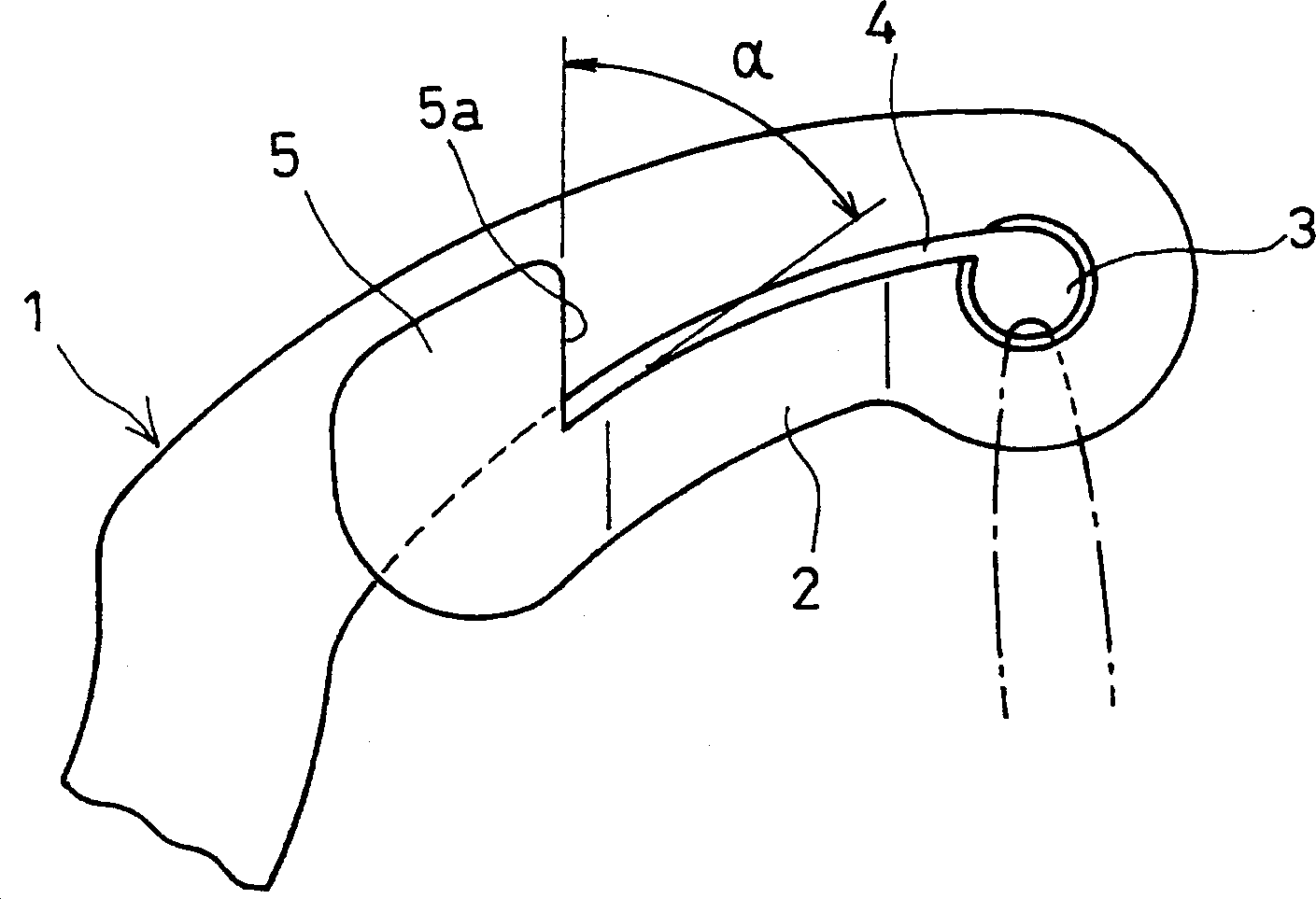
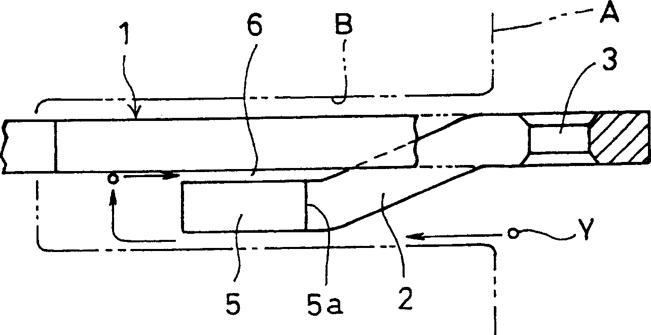
[0023] Below, refer to Figure 1 to Figure 3 Examples of the present invention will be described. As shown in the figure, the guide piece 2 is connected to the front end of the thread take-up lever body 1 , and the guide piece 2 is bent downward about 180° and is arranged below the front end of the thread take-up lever body 1 . At the connecting portion between the guide piece 2 and the thread take-up lever body 1, a thread hole 3 penetrating in the thickness direction is provided.

[0024] In addition, a wire hole 4 communicating with the above-mentioned wire hole 3 is formed between the upper edge of the guide piece 2 and the lower edge of the front end portion of the thread take-up lever body 1 .

[0025] At the front end portion of the guide piece 2, an upward suture introduction piece 5 is provided, and the suture introduction piece 5 is opposite to one side of the thread take-up lever body 1, and there is a thread between the opposite parts to allow the suture to pass t...


PUM


Abstract

A guide piece 2 successively provided on the tip part of a needle thread take-up body 1 is bent roughly 180[deg.] downwards and the guide piece 2 is provided on the tip part lower side of the needle thread take-up body 1. A thread hole 3 passed through in a thickness direction is provided on the connection part of the guide piece 2 and the needle thread take-up body 1 and a thread leading hole 4 communicating with the thread hole 3 is formed between the upper edge of the guide piece 2 and the lower edge of the needle thread take-up body 1. A thread introducing piece 5 facing one side face of the tip part of the needle thread take-up body 1 and forming a gap 6 through which the thread can be inserted between the facing parts is provided on the tip part of the guide piece 2. The thread inserted to the thread hole 3 is prevented from falling out from the thread leading hole 4 by the thread introducing piece 5 and the thread abutting on one side face of the needle thread take-up main body 1 is inserted to the thread hole 3 by drawing it to the side of the thread hole 3.

Description

technical field [0001] The invention relates to a thread take-up lever of a sewing machine. Background technique [0002] Such as Figure 4 and Figure 5 The thread take-up lever of the sewing machine shown has been known from the past. The thread take-up lever has a guide piece 12 formed on the upper side of the front end of the thread take-up body 11, and a thread hole 13 passing through the thickness direction of the guide piece 12 and the connection portion of the thread take-up body 11 is provided. A wire hole 14 communicating with the wire hole 13 is formed between the lower edge of the guide piece 12 and the upper edge of the front end of the thread take-up body 11 . [0003] However, on the above-mentioned conventional thread take-up lever, when it swings downward and the suture passing through the thread hole 13 is slack, the suture will come out from the thread hole 13 through the guide wire hole 14 . [0004] In order to solve this problem, it is proposed to fo...

Claims


Application Information

Patent Timeline
IPC IPC(8): D05B49/00
Inventor 山崎范夫
Owner AXE YAMAZAKI
Why Eureka
Try Eureka