Optical disc device
An optical disc device and optical disc technology, applied to optical recording systems, recording of information on magnetic discs, optical recording/reproduction, etc., can solve problems such as inability to reproduce, reduce reading errors, and reduce the probability of inability to correct Effect
- Summary
- Abstract
- Description
- Claims
- Application Information
AI Technical Summary
Problems solved by technology
Method used
Image

Examples
Embodiment 1
[0026] Next, Embodiment 1 of the present invention will be described with reference to the drawings.
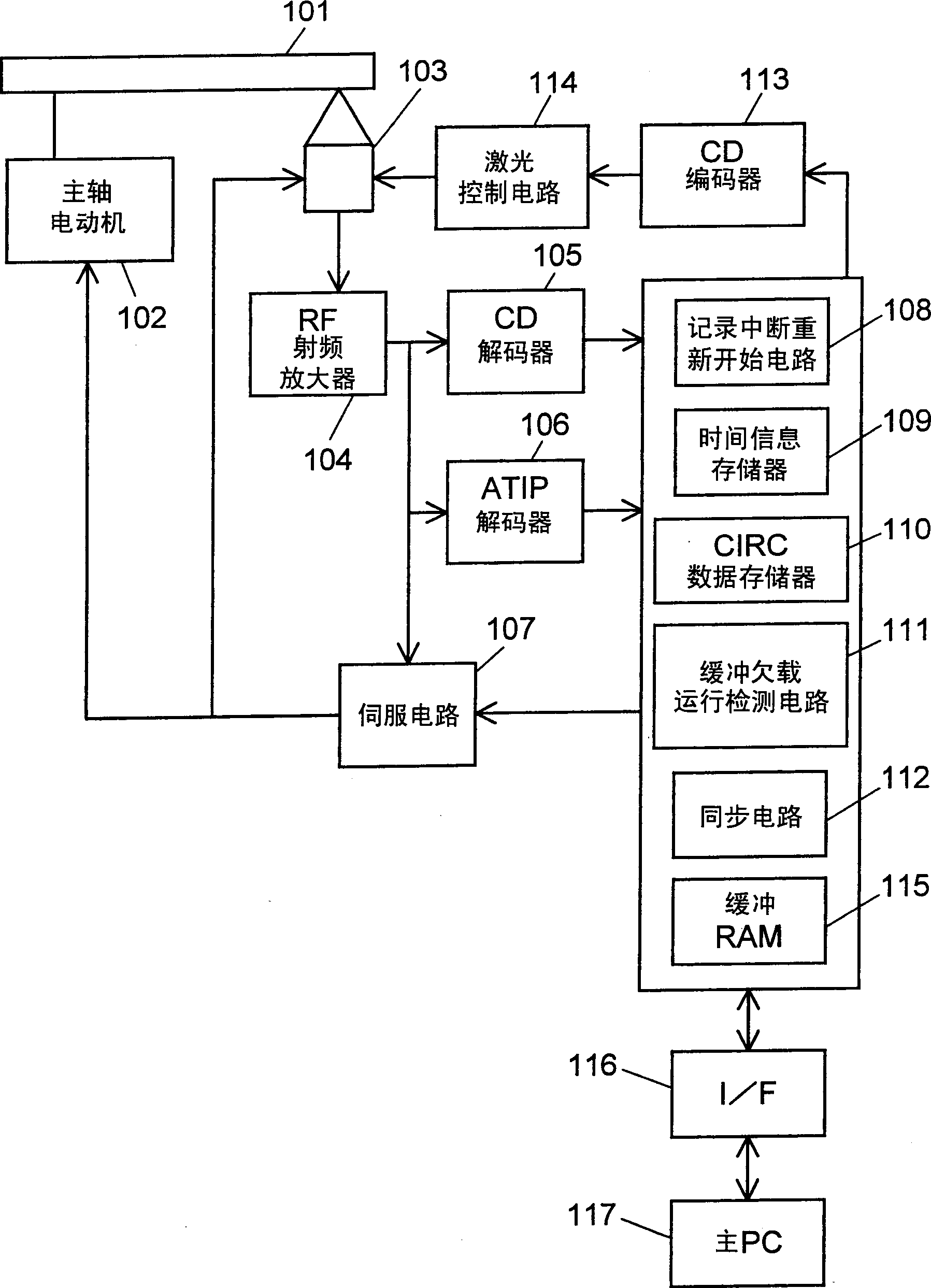
[0027] figure 1 It is a block diagram showing the configuration of the optical disc device in the present invention. exist figure 1 Each constituent element is described in .
[0028] The optical disc 101 is an information recording medium on which data is recorded. More specifically, it is an optical disc such as CD-R, CD-RW, DVD-R, and DVD-RW, and is an optical disc having a recordable information recording layer. In the following description, CD-R (CD-Recordable) and CD-RW (CD-Rewritable) based on the CD standard will be described as examples.
[0029] The spindle motor 102 is a rotary drive device that drives and rotates the optical disc 101 . The optical pickup 103 irradiates laser light on the recording surface of the optical disc 101, records on the optical disc 101 or detects reflected light from the optical disc 101, and reproduces information.
[0030] The RF ...
Embodiment 2
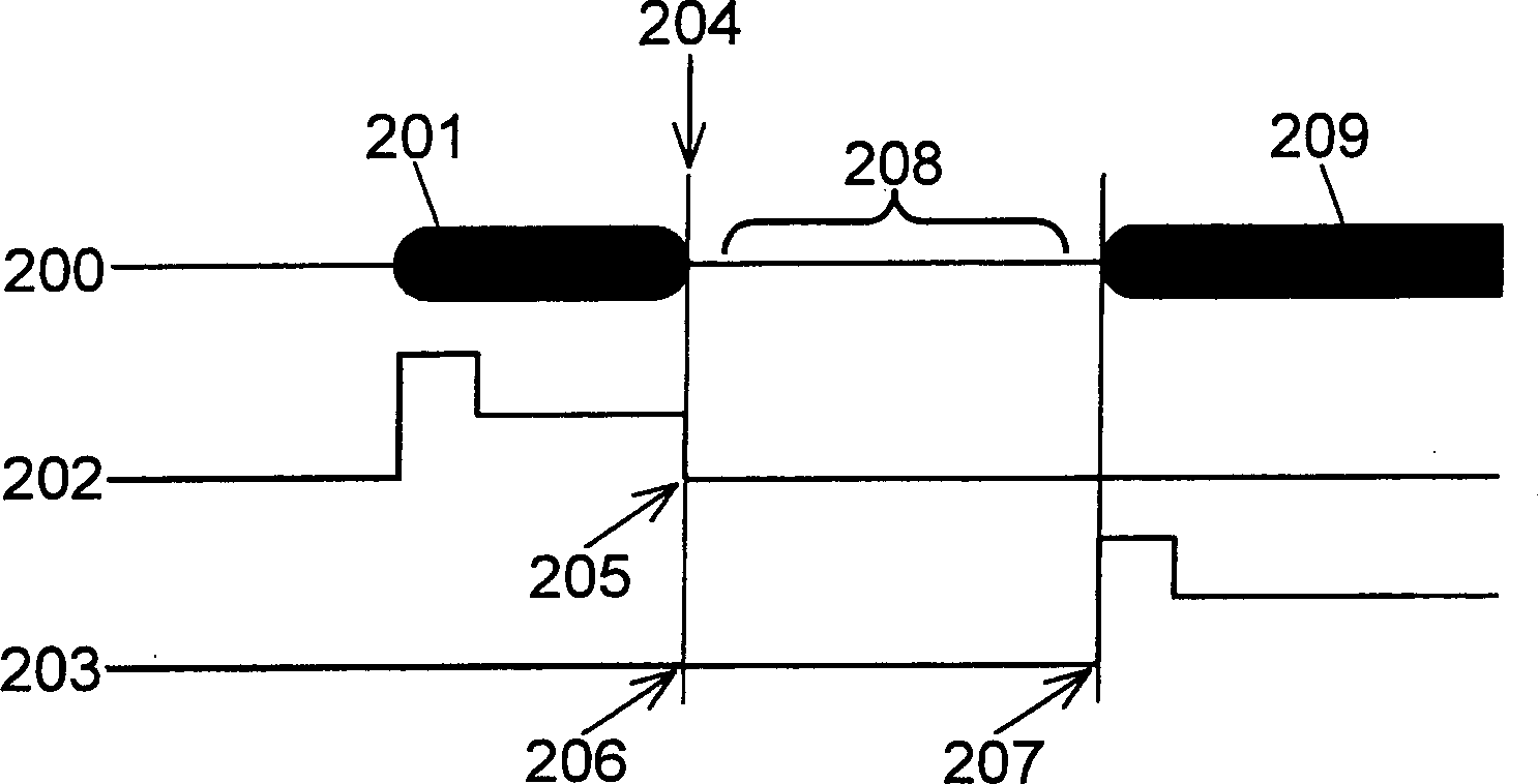
[0058] In this embodiment, the mechanism of the optical disk device uses figure 1 Structure. Figure 4 It is a figure explaining the resuming position of the recording interruption in Embodiment 2, and it expresses by figure 1 In the CD encoder 113, the record data is synchronized with the reference clock, and the state is arranged in order. Figure 4 Data 301 to be recorded on the optical disc 101 is shown. A frame 302 is a recording data sequence composed of 588 channel bits. In general, recording data is usually composed of a plurality of frames 302, and one frame 302 represents the smallest unit thereof.
[0059] The frame pit signal 303 is arranged at the head of one frame 302, and is used to synchronize the recording data with the reference clock in the optical disc device at the time of reading.
[0060] In addition, in Figure 4 Among them, the recording data 304 represents the recording data already recorded on the optical disc 101 and the recording data actually...
Embodiment 3
[0086] Next, in Embodiment 3, the operation of interrupting and resuming recording on the optical disc 101 by the optical disc device in Embodiment 3 will be described.
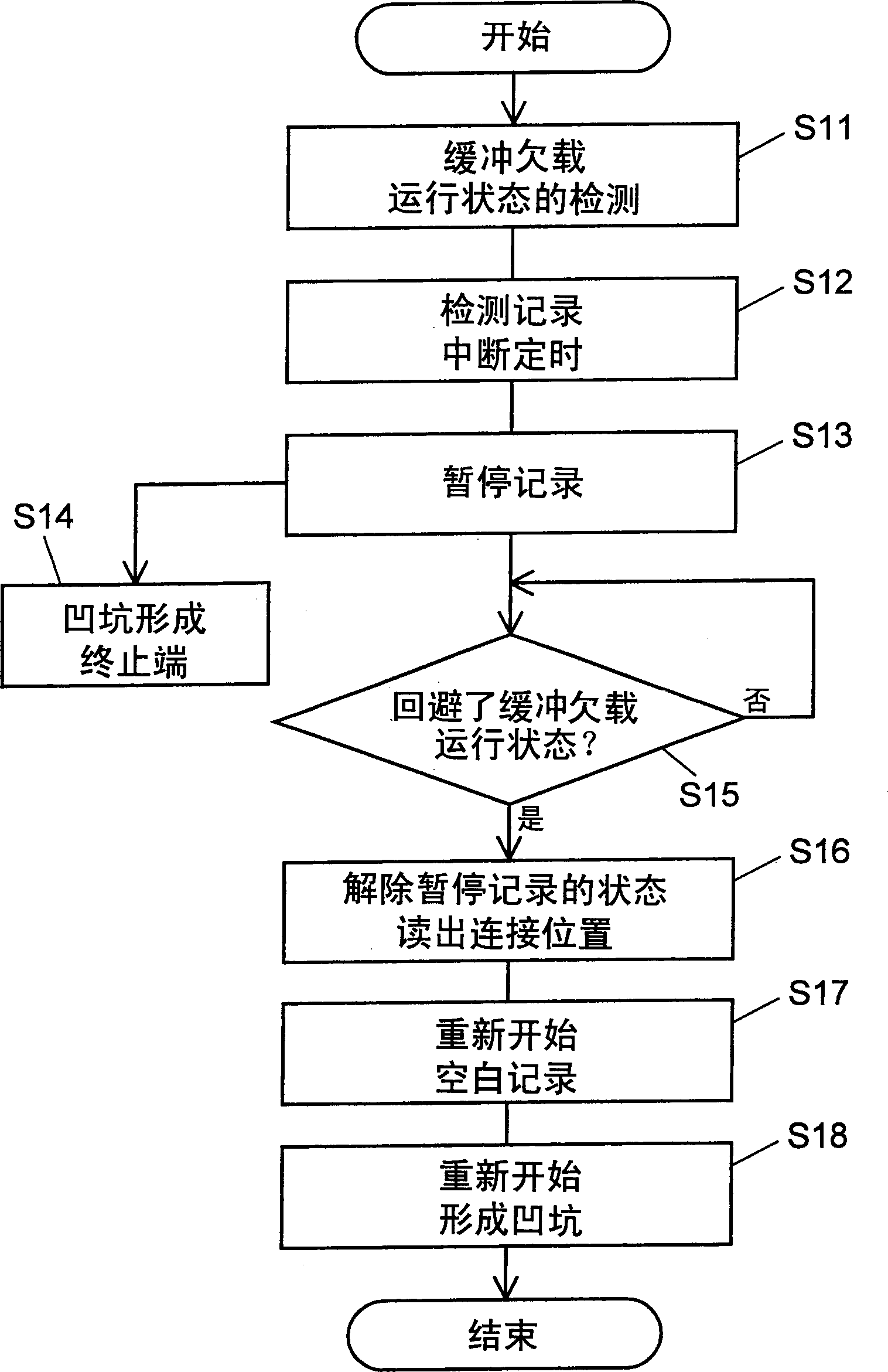
[0087] Figure 7 It is a program flow chart illustrating the interruption and resumption of recording in the third embodiment. Using in explanation so far figure 1 , figure 2 , Figure 4 Also applies to Example 3. exist figure 1 , figure 2 , Figure 4 as well as Figure 7 In this case, the recording and interruption to the optical disc 101 are carried out within the backward range from the end of one frame to the maximum correctable number of the optical disc, and at the connection position after the formation of the continuous pits 201 is completed.
[0088] First, if the remaining amount of data in the buffer RAM 115 becomes less than a predetermined amount, the buffer underrun detection circuit 111 detects the buffer underrun state, and notifies the record interrupt restart circuit 108 of the buf...
PUM
 Abstract
Description
Claims
Application Information
 - R&D
- Intellectual Property
- Life Sciences
- Materials
- Tech Scout
- Unparalleled Data Quality
- Higher Quality Content
- 60% Fewer Hallucinations
Browse by: Latest US Patents, China's latest patents, Technical Efficacy Thesaurus, Application Domain, Technology Topic, Popular Technical Reports.
© 2025 PatSnap. All rights reserved.Legal|Privacy policy|Modern Slavery Act Transparency Statement|Sitemap|About US| Contact US: help@patsnap.com