Drawbench for drawing long and thin material

A technology of slender materials and drawing machines, which is applied in the field of drawing machines, can solve the problem that the stroke frequency cannot be increased arbitrarily, and achieve the effect of cost saving

Inactive Publication Date: 2002-12-18
SMS MEER
View PDF2 Cites 2 Cited by
  • Summary
  • Abstract
  • Description
  • Claims
  • Application Information

AI Technical Summary

Problems solved by technology

However, the stroke frequency cannot be increased arbitrarily, as it is limited by the inertial forces generated at the turning point of the drawing carriage

Method used


Image

  • Drawbench for drawing long and thin material
  • Drawbench for drawing long and thin material
  • Drawbench for drawing long and thin material

Examples


Embodiment Construction

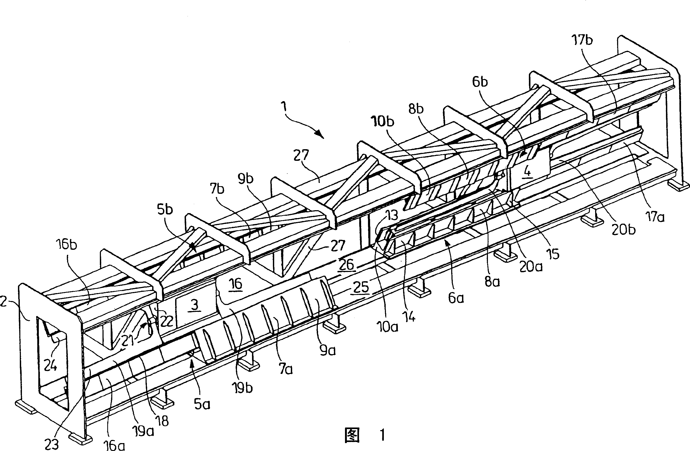
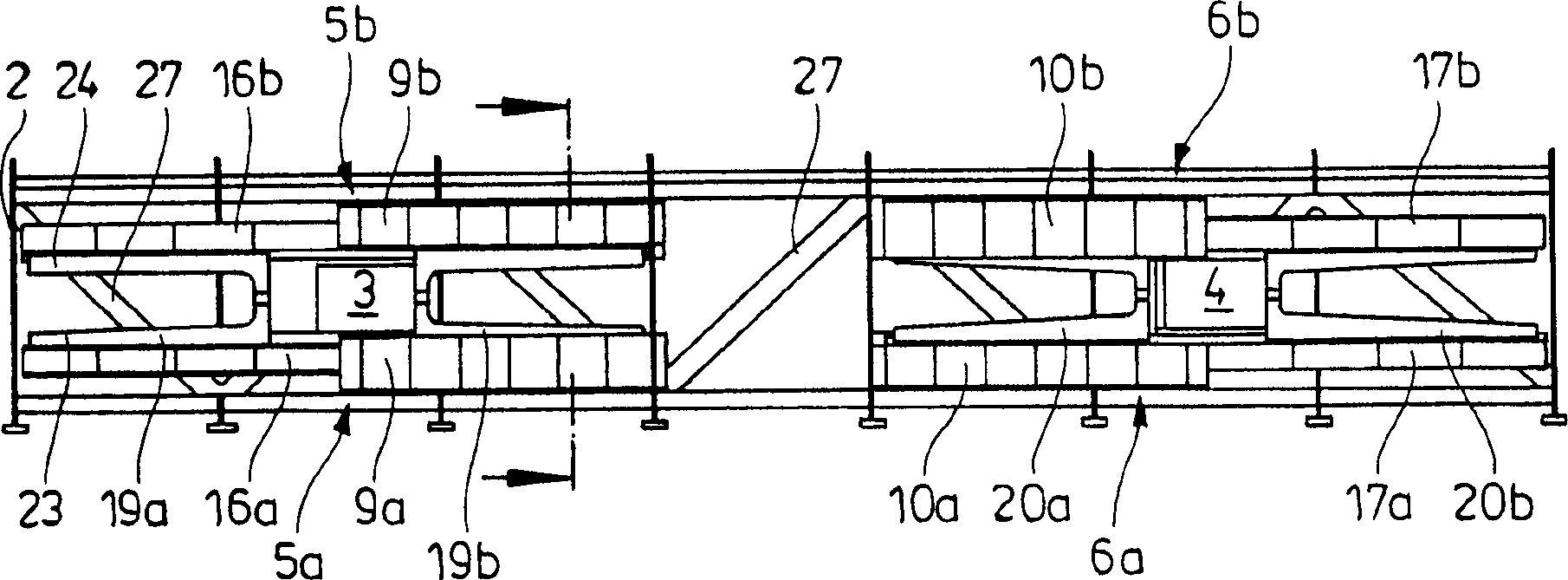
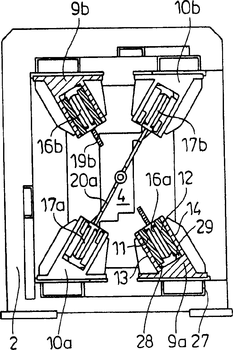
[0030] FIG. 1 shows a drawing machine with a frame 2 and a drawing unit arranged in the frame. The drawing unit consists of a drawing die (not shown) and two drawing carriages 3, 4, these two carriages operate in a hand-in-hand manner, and pull the drawing material through the drawing die, such as a Root canal or a rod (not shown). To this end, two drawing carriages 3, 4 (one of which may be a combined pre-drawing and drawing carriage) are each driven by two linear motor drives 5a, b; It moves along a track formed by a linear motor drive in the direction. The track is part of two linear motor drives comprising a first (upper) and a second (lower) track section 7b, 8b; 7a, 8a. In the embodiment shown, the track sections 7a, b; 8a, b are formed by fixed primary parts of the linear motor drives 5a, b; 6a, b. One (7b, 8b) of the two track parts is fixed on the upper part of the frame 2, and the other (7a, 7b) is fixed on the lower part of the frame 2. The two track parts are d...


PUM


Abstract

The drawing machine (1) comprises a drive for each drawing carriage (3,4), and has at least two linear motor drives (5a,b,6a,b) with primary and secondary parts. The machine frame (2) has a track which extends in the drawing direction for the respective drawing carriages. The track is part of the linear motor drives, and has a first, top part (7b,8b) and a second, bottom part (7a,8a).

Description

technical field [0001] The invention relates to a drawing machine with a frame and a drawing unit for drawing elongated material through a drawing die, in particular for reducing the cross-section, said drawing unit having at least one A puller carriage and a drive for the puller carriage. [0002] Drawing machines are used to draw slender metal objects such as tubes, wires or rods through a drawing die. Drawing machines are divided into continuously operating drawing machines, in which the length of the drawn part exceeds several times the machine size, and intermittently operating drawing machines, such as wire drawing machines. Background technique [0003] An example of a continuously operating linear drawing machine is disclosed in DE-OS2852071. This document discloses a carriage drawing machine with a drawing unit, which has two drawing carriages that can slide parallel to the drawing direction on slides mounted on the frame. The two relatively reciprocating drawing...

Claims


Application Information

Patent Timeline
IPC IPC(8): B21C1/16B21C1/10B21C1/28B21C1/30
CPCB21C1/30B21C1/305B21C1/10
Inventor H·-J·克林根N·茨勒肯斯R·邦塞尔斯T·温特菲尔德特
Owner SMS MEER
Why Eureka
Try Eureka