
Wind power device

A technology of wind power equipment and wind direction, applied in the direction of mechanical equipment, wind power engine, wind power motor combination, etc., can solve problems such as asymmetry, achieve the effect of suppressing spring effect, simple torque control, and suppressing undesired effects

Inactive Publication Date: 2006-12-13
阿洛伊斯沃本
View PDF0 Cites 0 Cited by
  • Summary
  • Abstract
  • Description
  • Claims
  • Application Information

AI Technical Summary

Problems solved by technology

If more than one, for example four, azimuth drives are mounted on the periphery of a tower bearing with an integral tooth structure, slight variations in the tooth profile at the periphery of the tower can lead to severe asymmetries

Method used


Image

  • Wind power device
  • Wind power device
  • Wind power device

Examples


Embodiment Construction

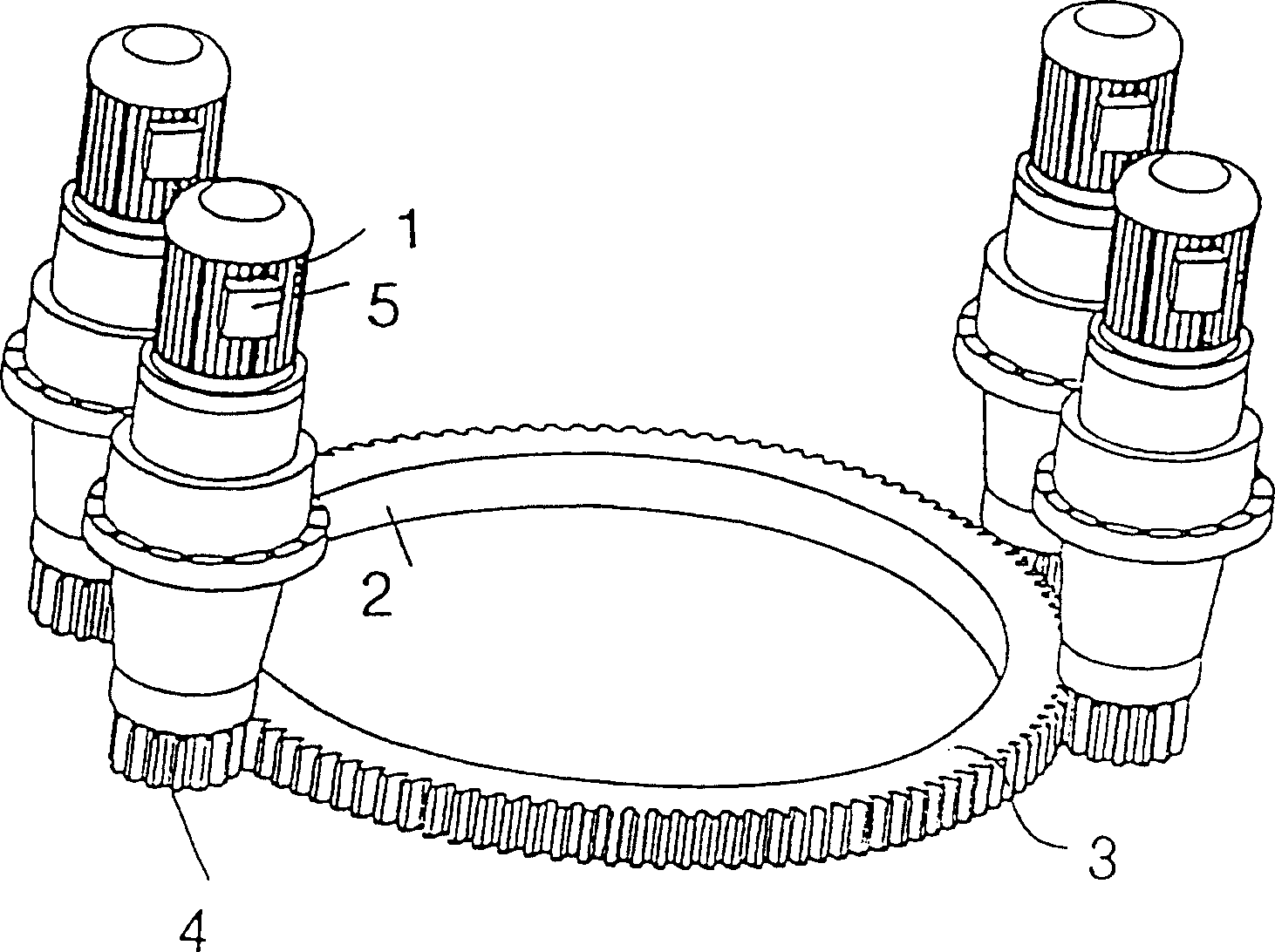
[0035] Wind power plants often have dynamic drives for wind direction tracking. The dynamic drive turns the nose of the wind turbine so that the rotor blades of the rotor are optimally positioned in the direction of the wind. The dynamic drive used for wind direction tracking is an azimuth drive 1 with associated azimuth bearing 2 and is usually arranged between the tower top and the casing. In the case of small wind turbines, one azimuth drive is sufficient, while large wind turbines usually have several drives, e.g. figure 1 The four drives shown in . The four drives are evenly distributed along the perimeter of the tower top 3 (a non-uniform distribution is also possible).

[0036] During operation of wind power plants in strong winds, depending on the angle of rotation of the rotor, very large forces are generated and associated with this high and frequent load peaks in the azimuth drive.

[0037] If the movement device used to move the handpiece has more than one azim...


PUM


Abstract

Wind power installations generally have an active drive for wind direction tracking. The active drive rotates the machine housing of the wind power installation in such a way that the rotor blades of the rotor are oriented in the direction of the wind. That drive which is required for wind direction tracking is generally an azimuthal drive which is usually disposed with the associated azimuthal bearings between the pylon top and the machine housing. One displacement drive is sufficient when small wind power installations are involved, while larger wind power installations are generally equipped with a plurality of azimuthal drives. The object of the invention is to improve the azimuthal drive for wind power installations so that the above-indicated problems are eliminated, to provide a structurally simple azimuthal drive, to ensure uniform load distribution for each azimuthal drive, and to prevent unwanted torque fluctuations in the individual drives. A wind power installation comprising a machine housing which accommodates a rotor with at least one rotor blade and a displacement device for displacement of the machine housing for desired orientation of the rotor in the direction of the wind, wherein the displacement device has as a drive a three-phase asynchronous motor which for displacement of the machine housing is acted upon by a three-phase current of variable frequency.

Description

technical field [0001] The invention relates to an azimuth drive for a wind power installation. Background technique [0002] Wind power installations usually have dynamic drives for wind direction tracking. The dynamic drive rotates the casing of the wind power plant and positions the rotor blades of the rotor in the direction of the wind. The drive required for wind direction tracking is generally an azimuthal drive, which is usually arranged between the pylon or tower top and the casing together with associated azimuthal bearings. When it comes to small wind turbines, one mobile drive is sufficient, but larger wind turbines are often equipped with multiple azimuth drives. [0003] During the wind direction tracking process of the chassis, the wind measuring operating system provides an average value of the wind direction within a certain period of time, for example, 10 seconds. This average is repeatedly compared to the instantaneous azimuth position of the enclosure. ...

Claims


Application Information

Patent Timeline
IPC IPC(8): F03D7/02F03D11/00H02P3/24H02P5/74F03D7/04
CPCF03D11/00F03D7/0204F05B2270/20Y02E10/723Y02E10/722F03D80/00F03D80/70Y02E10/72F03D7/042F03D9/25F05B2240/21
Inventor 阿洛伊斯·沃本
Owner 阿洛伊斯沃本
Learn More