


Quick Research
Generate reliable direction feasibility study reports for your R&D in just a few steps.

Technical Q&A
Discover and master advanced knowledge NOW. Basics, ideas, possibilities, all at once.

Find Solutions
As an expert in R&D theories, this can generate solutions to your technical problems instantly.

Evaluate Feasibility
Analyze your overall solution with one click, know your potential R&D risks in advance.

Monitor Landscape
Get weekly tech updates, stay abreast of the latest tech innovations and key insights.
Airplane with rotary wings
An aircraft and fuselage technology, applied in the field of rotary-wing aircraft, can solve the problems of use restrictions and low safety factors, and achieve the effects of large load capacity, low production and use costs, and easy operation.
- Summary
- Abstract
- Description
- Claims
- Application Information
AI Technical Summary
Problems solved by technology
Method used
Image

Examples
Embodiment Construction
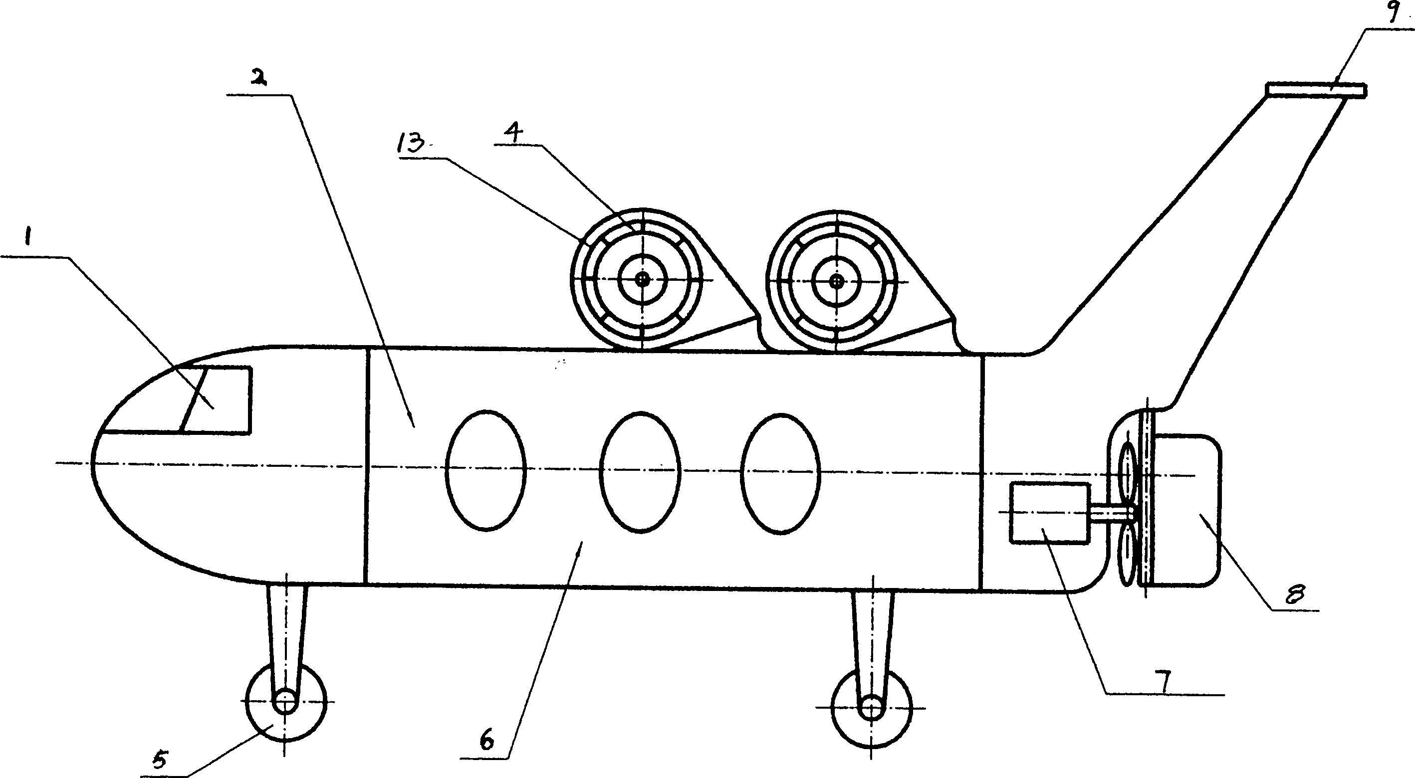
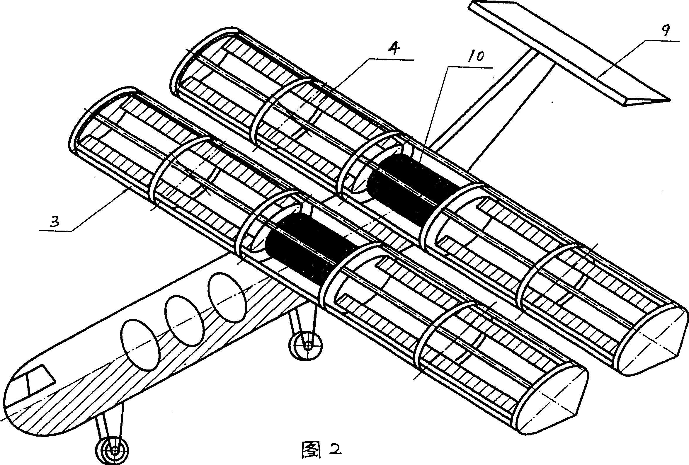
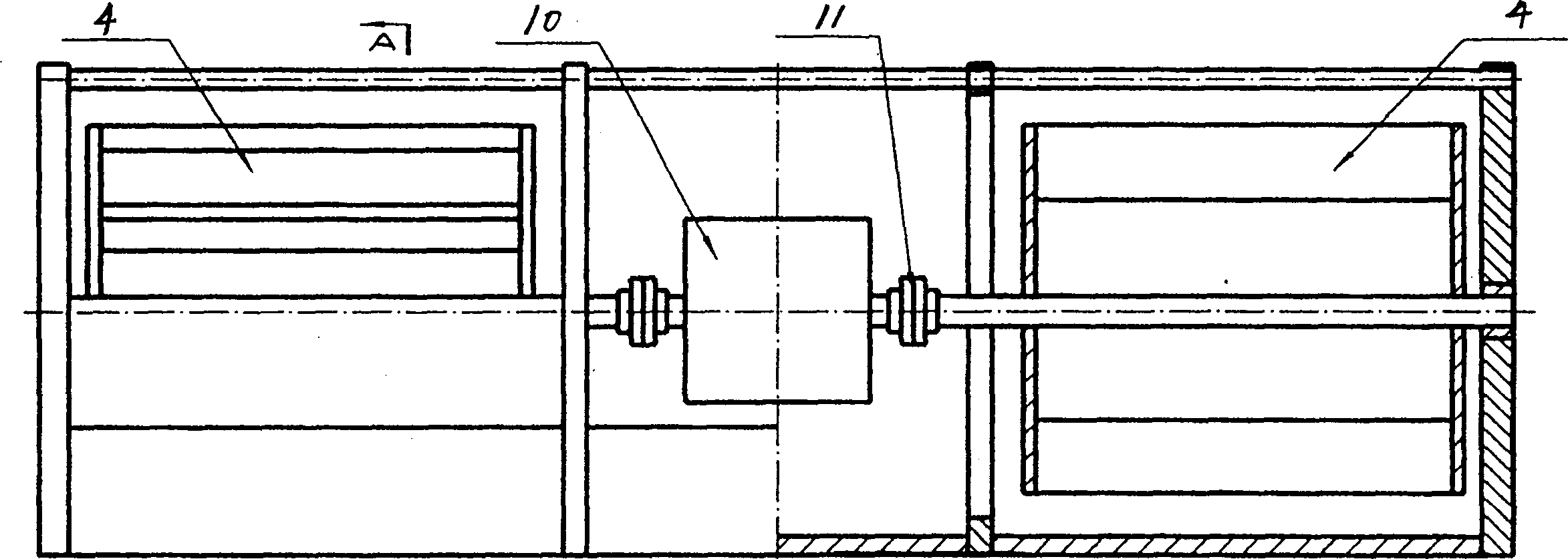
[0024] Such as figure 1 , 2, 3, and 4. Described rotorcraft comprises fuselage 6, empennage 9, tail 8 and the propeller propeller 7 positioned at fuselage afterbody, is fixed with two rotors 13 above the fuselage, each rotor 13's left, There is a cylindrical propeller 4 inside each right side, the shaft of the propeller 4 is connected with the engine 10 located at the back of the fuselage through a coupling 11, and an airflow port is opened at the front edge of the rotor wing 13, and the airflow port is sealed. The upper end of the cover is hinged on the secondary wing 3 on the rotor wing 13, which is used to control the access to the propeller.
[0025] The working principle of the above-mentioned rotary-wing aircraft is as follows:
[0026] After the engine engine 10 is started, it is driven by the coupling 11 to drive the cylindrical propeller impeller 4 to rotate, so that the air is sucked into the rotor 13 and lifted up so that the air pressure is higher than the rear e...
PUM
 Abstract
Description
Claims
Application Information
 - R&D Engineer
- R&D Manager
- IP Professional
- Industry Leading Data Capabilities
- Powerful AI technology
- Patent DNA Extraction
Browse by: Latest US Patents, China's latest patents, Technical Efficacy Thesaurus, Application Domain, Technology Topic, Popular Technical Reports.
© 2024 PatSnap. All rights reserved.Legal|Privacy policy|Modern Slavery Act Transparency Statement|Sitemap|About US| Contact US: help@patsnap.com