
Projection televisions with holographic screens having stacked elements

A technology of projection TV and screen, which is applied to optical components, image reproducers of projection devices, projection devices, etc., can solve the problem of no progress in color shift problem, and achieve the effect of improving color shift performance.

Inactive Publication Date: 2005-06-29
THOMSON LICENSING SA
View PDF8 Cites 0 Cited by
  • Summary
  • Abstract
  • Description
  • Claims
  • Application Information

AI Technical Summary

Problems solved by technology

[0022] In conclusion, although much development work has been done over the years to provide projection television receivers with screens with a color shift of less than 5, or even much less than 5, or with a color shift as low as 5 with an alpha angle greater than 10° or 11° , but unlike traditional projection screens with constant changes in the shape, position, and scatterer of convex lens elements, there has been no progress in solving the problem of color shift
Also, although 3D holographic elements have been suggested for use in projection screens, no attempt has been made to provide projection televisions with 3D holographic screens since no color cast was involved
Thus, there is a long felt need for a projection television receiver with greatly improved color shift performance that can be packed into a smaller enclosure.

Method used


Image

  • Projection televisions with holographic screens having stacked elements
  • Projection televisions with holographic screens having stacked elements
  • Projection televisions with holographic screens having stacked elements

Examples


Embodiment Construction

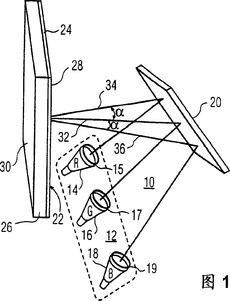
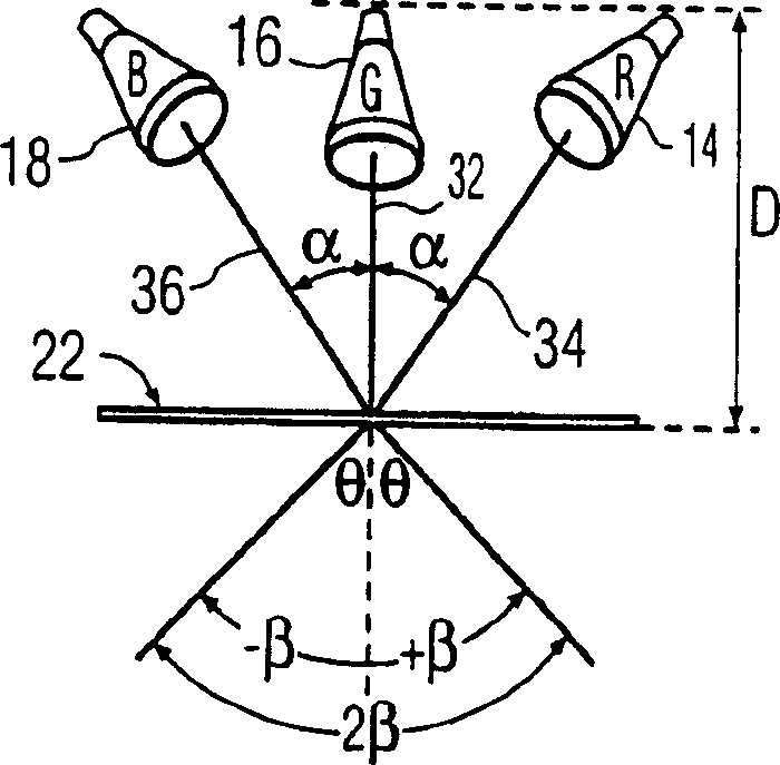
[0038] FIG. 1 schematically shows a projection television receiver 10 . Projection cathode ray tubes 14, 16 and 18 arranged in array 12 produce red, green and blue images, respectively. These cathode ray tubes are also provided with respective lenses 15 , 17 and 19 . The projected image is reflected by the mirror 20 onto the projection screen 22 . Additional mirrors can also be used according to the specific structure of the optical path. Green cathode ray tube 16 projects a green image along optical path 32, which is oriented substantially normal to the screen. In other words, the centerline of the light path is at right angles to the screen. The red and blue cathode ray tubes have optical paths 34 and 36, respectively, which converge toward the first optical path 32 at an angle of incidence a in a non-orthogonal orientation. This angle of incidence causes the problem of color shift.

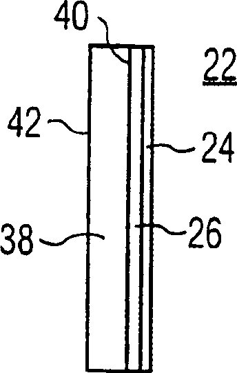
[0039] The screen 22 includes a three-dimensional holographic element 26 arranged on a...


PUM


Abstract

A television projection screen (22) has a three-dimensional holographic element (26) disposed on a film substrate (24). The screen (22) may have a plurality of stacked holographic elements and / or Fresnel lenses with varying optical properties in the vertical and horizontal directions respectively. For example, vertical and horizontal holographic elements may have varying gains over a horizontal viewing angle of ±40° and a vertical viewing angle of ±20°. At least one projection tube (14, 18) is oriented along a light path (34, 36) converging at an angle a to a line or axis normal to the screen. The holographic elements form an interference pattern that effectively reduces color shifts in the displayed image that would otherwise result from off-axis projection. The screen (22) has a color shift less than or approximately equal to 5 at an angle α between about 0° and 30°.

Description

technical field [0001] The present invention relates generally to the field of projection television receivers, and more particularly, the present invention relates to a projection television receiver having a display screen with substantially reduced color shift and / or reduced cabinet depth. Background technique [0002] Color shift is defined as the red / blue or green / green color shift of the white image formed by the projected images from the red, green, and blue projection tubes at the center of the projection screen, measured at the maximum brightness position of the vertical viewing angle. The blue scale changes at different horizontal viewing angles. [0003] The color shift problem is caused by requiring at least three image projectors for images of different colors (eg red, blue and green). A projection screen receives images from at least three projectors on a first side and displays these images on a second side by controlling light disper...

Claims


Application Information

Patent Timeline
IPC IPC(8): G02B5/32G03B21/62H04N9/31G03B21/56
CPCG02B5/32H04N9/31
Inventor 小E·T·哈尔W·R·普菲勒
Owner THOMSON LICENSING SA
Learn More