Floor mop

A technology of mop and mop rod, which is applied in the field of mop and can solve problems such as difficulties in the extrusion process

Inactive Publication Date: 2005-06-22
CARL FREUDENBERG KG
View PDF4 Cites 0 Cited by
  • Summary
  • Abstract
  • Description
  • Claims
  • Application Information

AI Technical Summary

Problems solved by technology

But since the two rag wing supports are directly hinged to each other and the distance between the two rollers is very small, the extrusion process is very difficult, at least initially

Method used


Image

  • Floor mop
  • Floor mop
  • Floor mop

Examples


Embodiment Construction

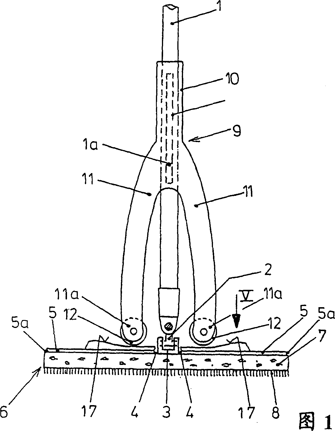
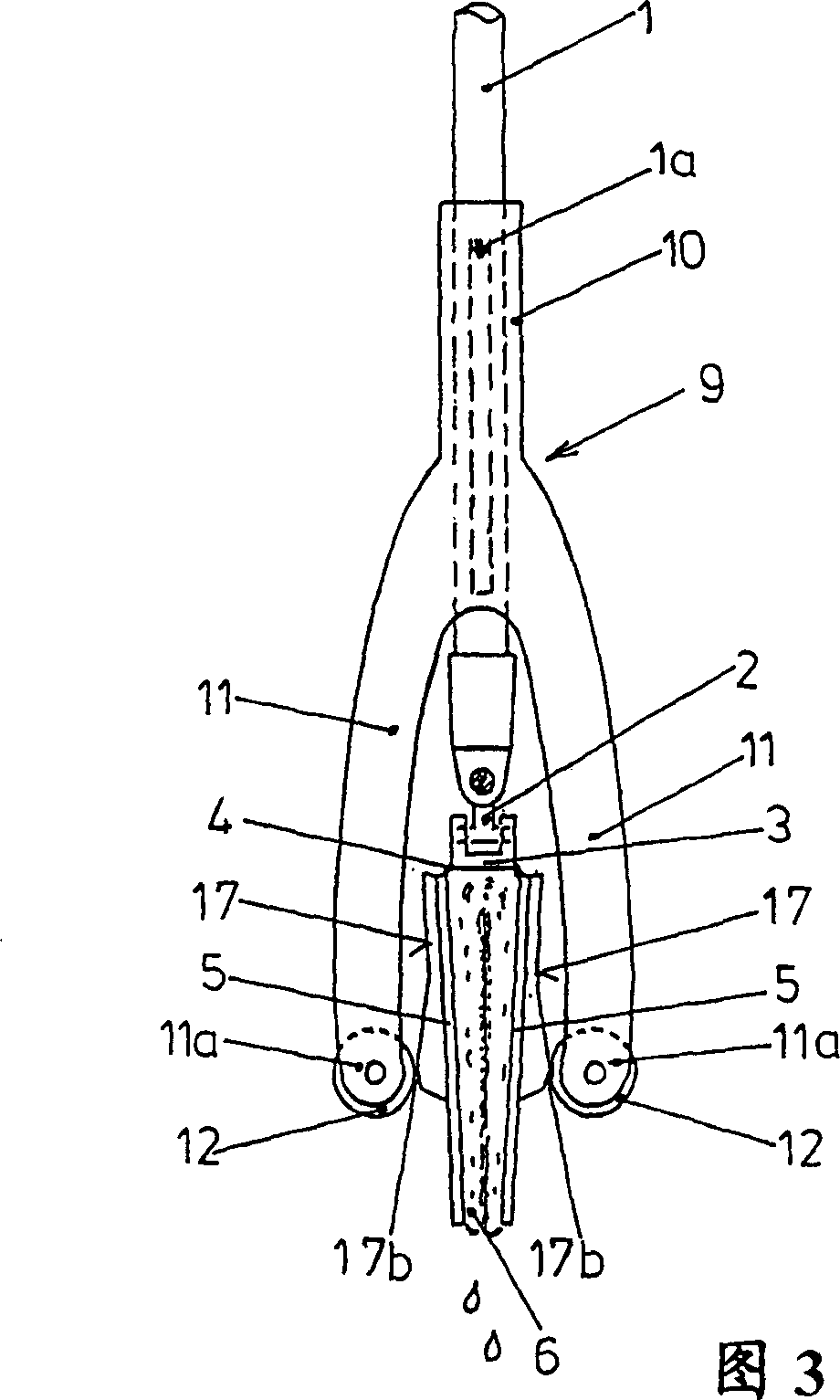
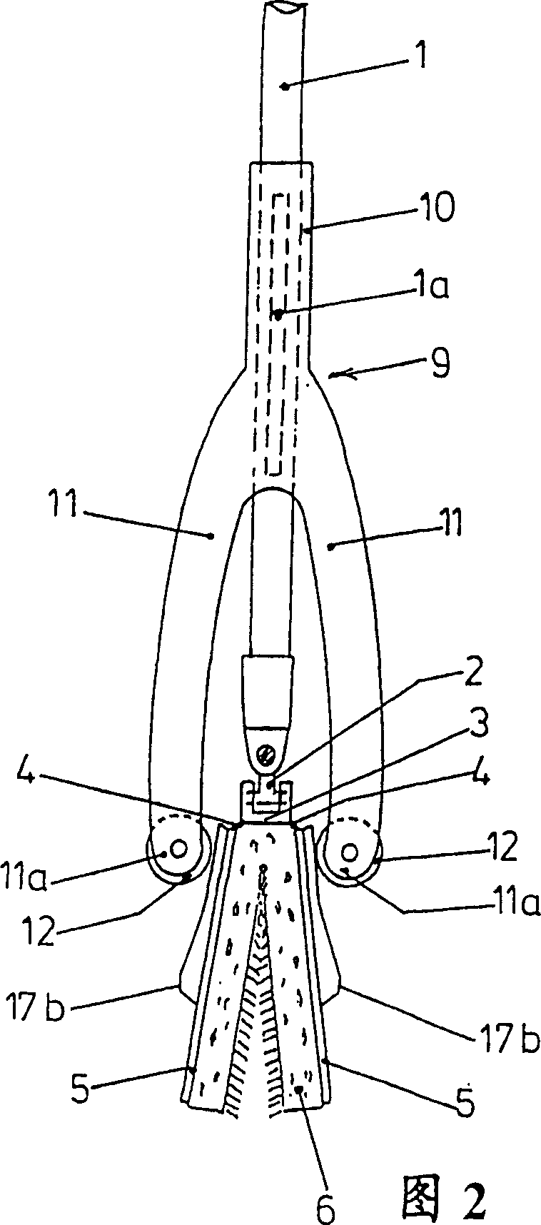
[0031] The mop shown in FIGS. 1 to 5 has a mop shaft 1 which is connected via a universal joint 2 to a support center part 3 in a non-rotatable but pivotable manner in all directions. The bracket central piece 3 is respectively connected with a mop wing-shaped bracket 5 through hinges 4 installed on both sides.

[0032] The two mop wing supports 5 and the support center piece 3 carry a water-absorbing, wringable wiper lining 6 which usually consists of a foam layer 7 and a fleece cover 8 .

[0033] The pressing slide 9 is displaceable along the mop rod 1 , and the pressing slide 9 has a guide sleeve 10 which is non-rotatably movable longitudinally on the mop stick 1 . For example, a longitudinal groove 10a is provided in the bore of the guide sleeve 10, in which the pin 1a mounted on the mop rod 1 engages.

[0034] The guide bush 10 is rigidly connected to two pressing arms 11, which in the exemplary embodiment shown in FIGS. 12.

[0035] In FIG. 6 it is shown that the roll...


PUM


Abstract

The mop has two mop wing-shaped supports (5) articulated with a common support center piece (3) and carrying a water-absorbent wiping liner (6). The mop rod (1) is hinged to the center piece (3) of the bracket through a universal hinge (2). A squeezing slider (9) that can move along the mop rod (1) but cannot rotate has two rigid squeezing arms (11), the ends (11a) of which can be connected to each matching mop through a roller (12). The guide surface (17) on the back of the wing bracket (5) interacts with it. Each mop wing bracket (5) forms a right-angled trapezoid or triangle. The edges distributed at right angles to the hinge edges of each mop wing bracket (5) form a common linear continuous front edge.

Description

technical field [0001] The present invention relates to a mop having two mop wing supports hinged to the mop shaft, supporting a mop-absorbent mopping liner, and a mop with two rigid squeeze arms movable along the mop shaft. Squeeze the slide block, and the ends of the extrusion arms can interact with the guide surfaces on the back of each matching mop wing-shaped support respectively. Background technique [0002] Mops with two mutually foldable mop wing holders for squeezing the mop liner, also known as butterfly mops, are known in different embodiments. In the mop according to US-A-5 483 720 and PCT / US95 / 10759, a cover that can move along the mop rod is connected by a guide rod with two bow-shaped plates that are rotatably supported on the parts in the bracket, and they are in When the cover is moved, it slides along the backs of the two mop wing supports, thereby causing the wing supports to close together. But here the mop rod must be rigidly connected to the center p...

Claims


Application Information

Patent Timeline
Patent Type & Authority Patents(China)
IPC IPC(8): A47L13/146
CPCA47L13/146A47L13/258
Inventor G·M·伊尔塞
Owner CARL FREUDENBERG KG
Why Eureka
Try Eureka