
Combustion structure and engine with same

A combustion structure and combustion chamber technology, which is applied to combustion engines, internal combustion piston engines, engine components, etc., can solve problems such as complex pre-combustion chamber structures, and achieve complex pre-combustion chamber structures, simplified structures, and improved scavenging efficiency Effect

Pending Publication Date: 2022-08-05
CHINA FIRST AUTOMOBILE
View PDF7 Cites 0 Cited by
  • Summary
  • Abstract
  • Description
  • Claims
  • Application Information

AI Technical Summary

Problems solved by technology

[0004] The main purpose of the present invention is to provide a combustion structure and an engine with it, to solve the problem of complex structure of the pre-combustion chamber with scavenging in the prior art

Method used


Image

  • Combustion structure and engine with same
  • Combustion structure and engine with same
  • Combustion structure and engine with same

Examples


Embodiment 1

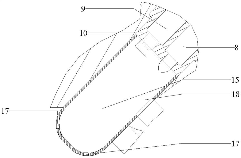
[0057] see Figure 8 , in this embodiment, the high-temperature mixed gas ignited in the pre-combustion chamber 15 can be injected into the combustion chamber 19 through the injection holes 17, there are two injection holes 17, and the two injection holes 17 are arranged at intervals along the first preset direction, In this way, the gas in the pre-chamber 15 can be uniformly injected into the combustion chamber 19 .

Embodiment 2

[0059] see Figure 9 , in this embodiment, the high-temperature mixed gas ignited in the pre-combustion chamber 15 can be injected into the combustion chamber 19 through the injection holes 17, and there are four injection holes 17, wherein the two injection holes 17 are spaced along the first preset direction The other two injection holes 17 are arranged at intervals along the second preset direction, so that the gas in the pre-combustion chamber 15 can be uniformly injected into the combustion chamber 19 .

Embodiment 3

[0061] see Figure 10 , in this embodiment, the high-temperature mixed gas ignited in the pre-combustion chamber 15 can be injected into the combustion chamber 19 through the injection holes 17, there are three injection holes 17, and the two injection holes 17 are arranged at intervals along the first preset direction, The third injection hole 17 is located between the other two injection holes 17 , so that the resistance of the gas in the pre-combustion chamber 15 to be injected into the combustion chamber 19 can be reduced.


PUM


Abstract

The invention provides a combustion structure and an engine with the same. The combustion structure comprises a cylinder body, and the cylinder body is provided with a combustion chamber and an air inlet channel communicating with the combustion chamber; the pre-combustion chamber is arranged on the cylinder body, and a first scavenging hole communicating with the air inlet channel is formed in the side wall of the pre-combustion chamber; the seat ring is arranged in the air inlet channel, the seat ring is connected with the pre-combustion chamber, and a second scavenging hole communicated with the first scavenging hole is formed in the seat ring; and the air inlet valve component is movably arranged in the seat ring so as to block or release the second scavenging hole, and the combustion structure solves the problem that the structure of the precombustion chamber with scavenging is complex.

Description

technical field [0001] The present invention relates to the field of engines, in particular, to a combustion structure and an engine having the same. Background technique [0002] Compared with the main combustion chamber, the pre-combustion chamber of the engine is smaller in volume and more complex in structure. After internal combustion, high-temperature exhaust gas will be generated. Due to the small nozzle holes connecting the pre-combustion chamber and the main combustion chamber, the residual exhaust gas after the pre-combustion chamber is ignited cannot be ignited. In the exhaust stroke and the intake stroke of the next combustion, all are discharged to the main combustion chamber, resulting in a large residual exhaust gas coefficient in the pre-combustion chamber. A larger residual exhaust gas coefficient will lead to a decrease in the ignition energy of the pre-combustion chamber and misfire in the next cycle. The fuel oil needs to go through the atomization and e...

Claims


Application Information

Patent Timeline
Patent Type & Authority Applications(China)
IPC IPC(8): F02B19/10F02B25/00F01L3/22
CPCF02B19/1004F02B25/00F01L3/22Y02T10/12
Inventor 段加全李莹宫艳峰张连方王振喜宋志平朱立铭蔡东
Owner CHINA FIRST AUTOMOBILE
Learn More