
Steel rail probe development test method and test platform

A test method and a test platform technology, applied in the direction of measuring devices, instruments, scientific instruments, etc., can solve the problems of inability to judge the state of the probe wheel probe, long development cycle of the probe wheel, and high time cost, so as to improve the utilization rate and reduce defective products efficiency and cost reduction

Active Publication Date: 2022-07-29
GUANGDONG GOWORLD
View PDF4 Cites 0 Cited by
  • Summary
  • Abstract
  • Description
  • Claims
  • Application Information

AI Technical Summary

Problems solved by technology

[0003] Whether the probe is qualified or not depends on whether the damage can be detected on the rail. At present, conventional probes have to go through "development of probes - improvement of probes - assembly of finished probes - installation of finished probes on the flaw detection vehicle - rail flaw detection" This ultra-long process can only be evaluated by flaw detection testing, which makes the development cycle of the detection wheel relatively long and the development cost high
Since the probe wheel is tested, the bracket of the probe wheel has been installed inside the wheel skin, and the wheel skin has been filled with coupling fluid, it is impossible to judge the status of each probe in the probe wheel with the naked eye, even if a certain probe is detected to be incompatible Test requirements, also need to return to the factory to replace the probe, the time cost is very high

Method used


Image

  • Steel rail probe development test method and test platform
  • Steel rail probe development test method and test platform
  • Steel rail probe development test method and test platform

Examples


Embodiment Construction

[0043] Further description will be given below in conjunction with the accompanying drawings and the preferred embodiments of the present invention.

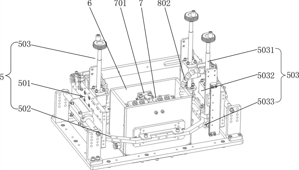
[0044] like figure 1 As shown, a rail probe development and test platform includes a rack 1, a test rail 2, two translation guide rails 3, a translation base 4, a tilt adjustment device 5, an open water tank 6, a probe mounting frame 7 and a coupling fluid circulation mechanism 8 ; The test rail 2 and the two translation guide rails 3 are arranged in parallel on the frame 1, and the test rail 2 is between the two translation guide rails 3; In this embodiment, the translation seat 4 is slidably installed through four sliders 401 On the translation guide rails 3 , each translation guide rail 3 corresponds to two sliding blocks 401 , and the translation base 4 is moved by manually pushing the translation bases 4 .

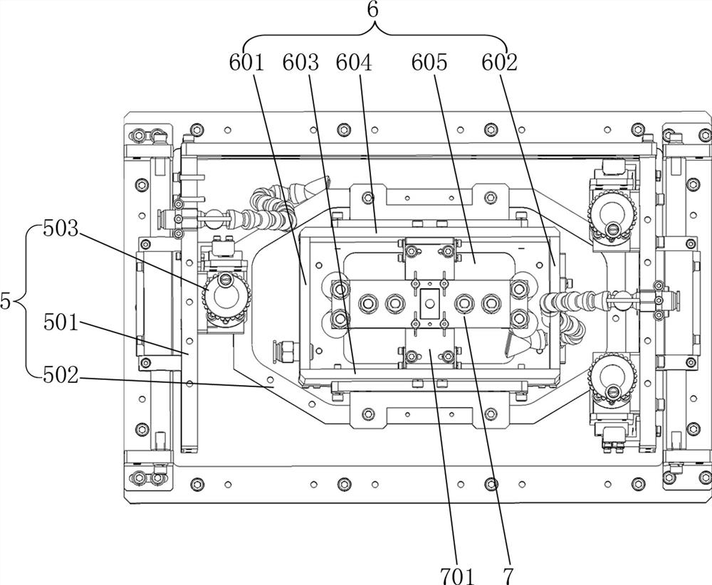
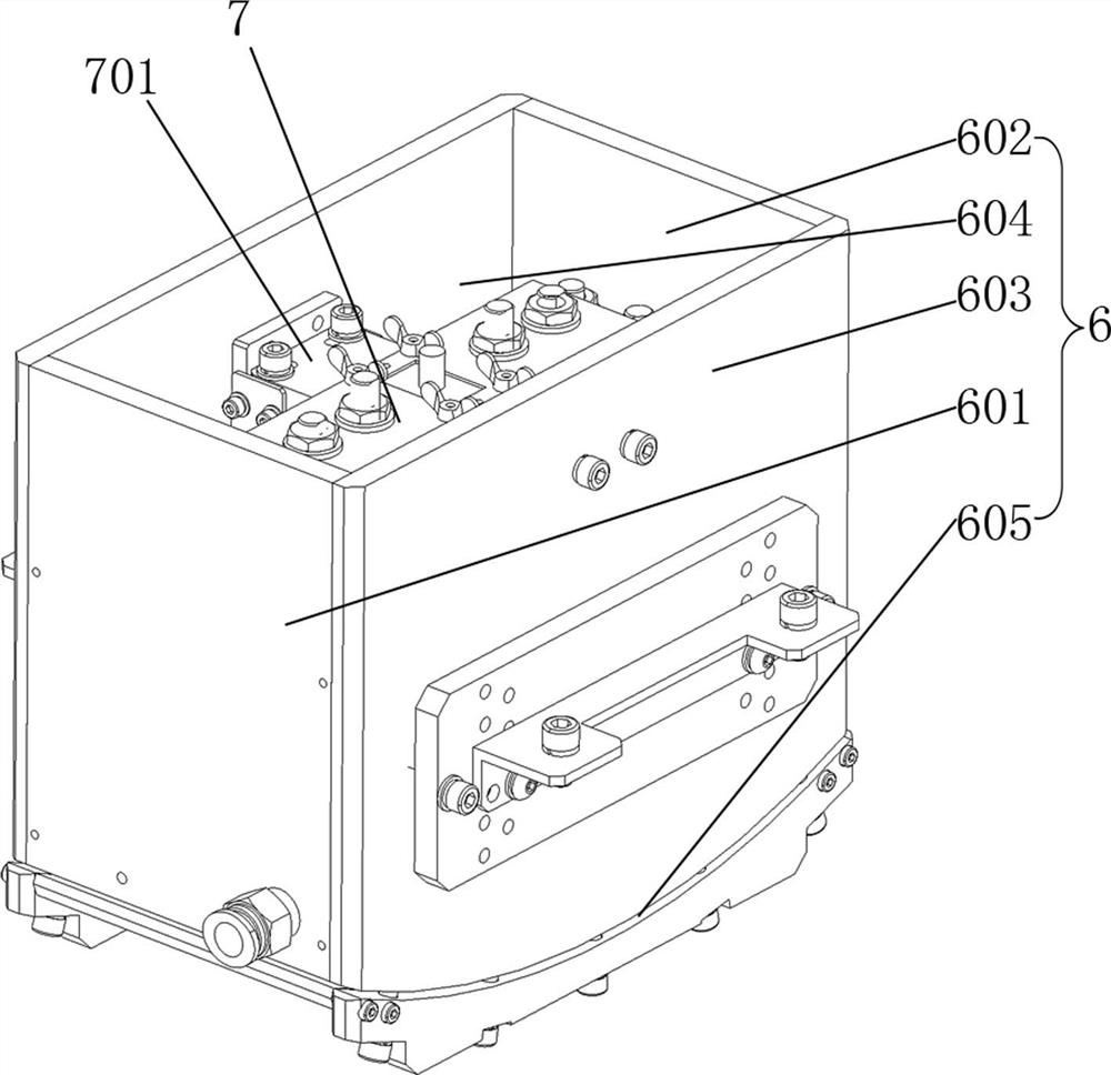
[0045] like Figure 1 to Figure 3 As shown, the tilt adjustment device 5 is installed on the translation base 4, an...


PUM


Abstract

The invention relates to a steel rail probe development test method and a test platform, and the method comprises the steps: simulating a detection wheel through an open water tank filled with coupling liquid, enabling the environment of a probe in the open water tank to be equal to the environment of the probe in the detection wheel, and enabling a tester to carry out the development test according to the test requirements; the probes can be rapidly and effectively installed, debugged and replaced in the open type water tank, the cost of the whole testing work is greatly reduced, the probes can be tested, debugged, improved and optimized one by one till the probes completely meet the requirements of the probe wheel, and then the probes are installed in the probe wheel and packaged. The performance test of the internal probe of the detection wheel after all the probes are mounted into the detection wheel is not needed, so that the defective rate of the finished detection wheel is greatly reduced; meanwhile, performance development of the probe is more convenient, once test data of a certain probe do not meet requirements, the probe can be independently improved and optimized, probe reproduction is not needed, and the development cost of the probe is further reduced.

Description

technical field [0001] The invention relates to the technical field of ultrasonic flaw detection, in particular to a development and testing method and a testing platform of a rail probe. Background technique [0002] As the detection component of the rail flaw detection vehicle, the ultrasonic probe is mainly used to detect the specified artificial damage on the rail. The probe wheel for rail ultrasonic flaw detection is equipped with nine single probes, including a 0° straight probe, two 37° oblique probes and six 70° oblique probes, of which the 0° straight probe is set in the middle, and the two 37° probes are located in the middle. The oblique probes are symmetrically arranged on the front and rear sides of the 0° straight probe, and the six 70° oblique probes are respectively arranged on the left front side, right front side, left rear side, right rear side of the 0° straight probe, and in front of the front 37° oblique probe. Lateral and posterior 37° oblique probe t...

Claims


Application Information

Patent Timeline
Patent Type & Authority Applications(China)
IPC IPC(8): G01N29/30G01N29/28
CPCG01N29/30G01N29/28G01N2291/0234
Inventor 陈志佳丁旭升陈伟杰吴金林郑燕峰周少武李佳陈坤裕许燚楷杨贵德
Owner GUANGDONG GOWORLD
Learn More