
Turbine rotor assembly dynamic balance indirect measurement method

A turbine rotor and measurement method technology, applied in the field of aero-engines, can solve problems such as difficulty in meeting engine vibration requirements, high labor intensity of workers, and low work efficiency, and achieve the effects of direct jump range, small workload, and high work efficiency

Pending Publication Date: 2022-07-29
CHINA HANGFA SOUTH IND CO LTD
View PDF0 Cites 1 Cited by
  • Summary
  • Abstract
  • Description
  • Claims
  • Application Information

AI Technical Summary

Problems solved by technology

[0005] The invention provides an indirect measurement method for the dynamic balance of the turbine rotor assembly, in order to solve the technical problems existing in the existing method that the workload is large, the labor intensity of the workers is high, the work efficiency is low, and it is difficult to meet the vibration requirements of the engine

Method used


Image

  • Turbine rotor assembly dynamic balance indirect measurement method
  • Turbine rotor assembly dynamic balance indirect measurement method
  • Turbine rotor assembly dynamic balance indirect measurement method

Examples


Embodiment Construction

[0027] The embodiments of the present invention will be described in detail below with reference to the accompanying drawings, but the present invention can be implemented in many different ways as defined and covered below.

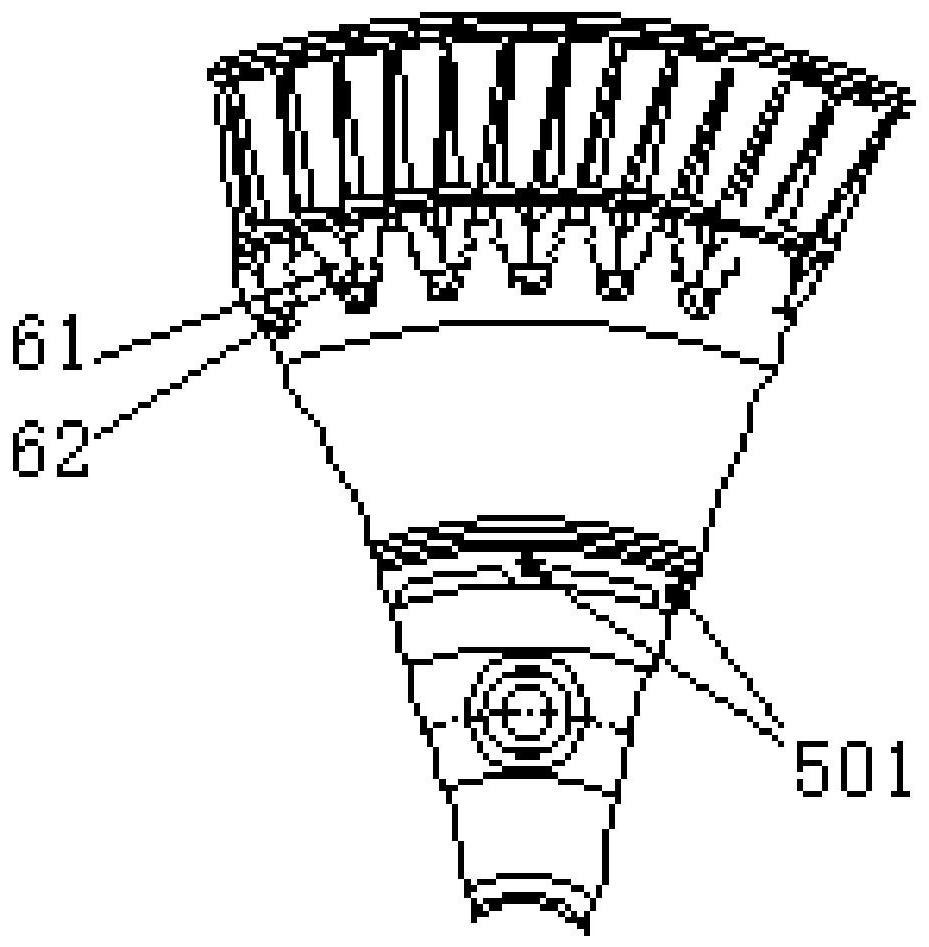
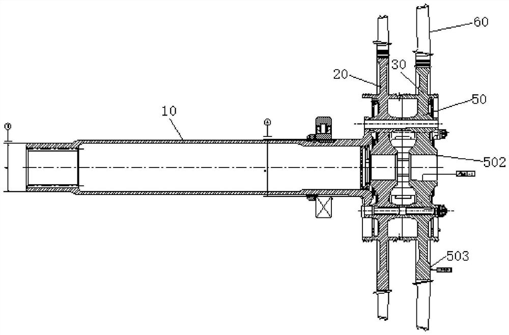
[0028] refer to Figure 2-Figure 4 , the preferred embodiment of the present invention provides an indirect measurement method for the dynamic balance of a turbine rotor assembly. The turbine rotor includes a turbine main shaft 10, and a first-stage rotor 20, a second-stage rotor 30 and a third-stage rotor installed on the turbine main shaft 10. The stage rotor 40, and the first stage rotor 20, the second stage rotor 30 and the third stage rotor 40 all include a turbine disk 50 installed on the turbine main shaft 10, and a plurality of groups of turbine disks 50 installed in sequence on the outer circumference The rotor blade 60, and each group of rotor blades 60 includes a left blade 61 and a right blade 62 that are matched and arranged, and the indirec...


PUM


Abstract

The invention discloses a turbine rotor assembly dynamic balance indirect measurement method. The method comprises the following steps: setting the weight difference between a left blade and a right blade of any group of rotor blades and the weight difference between two groups of rotor blades on any diameter; ensuring that the dynamic unbalance amount, the radial runout amount and the end runout amount of the turbine main shaft, the turbine rotor part and the turbine rotor respectively meet the requirements, and marking the number of a rotor blade corresponding to the maximum radial runout amount of the turbine rotor part and the position of the maximum end runout amount of the turbine rotor part; it is guaranteed that the radial jump amount, the end jump amount, the rotor blade corresponding to the maximum part of the radial jump amount, the difference value between the maximum part of the end jump amount and the radial jump amount and the end jump amount in dynamic balance, the position difference of the rotor blade corresponding to the maximum part of the radial jump amount and the position difference of the maximum part of the end jump amount meet the requirements respectively during final assembly of the turbine rotor. According to the indirect measurement method, the dynamic balance of the turbine rotor can be indirectly ensured to meet the requirement during final assembly, so that the workload is small, the labor intensity of workers is low, and the working efficiency is high.

Description

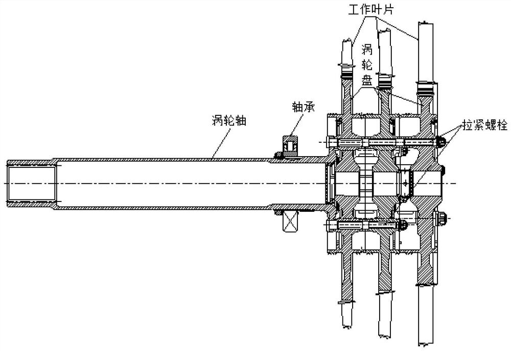
technical field [0001] The invention relates to the technical field of aero-engines, in particular to an indirect measurement method for dynamic balance of a turbine rotor assembly. Background technique [0002] The turbine rotor of a certain type of engine such as figure 1 As shown, it is mainly composed of turbine working blades 1, turbine discs 2, tension bolts 3, turbine shafts 4 and bearings 5. The engine uses the turbine rotor to do work to drive the compressor and the propeller. [0003] During the assembly process of the turbine rotor, static balance and dynamic balance tests are required to ensure that the dynamic unbalance of the turbine rotor is less than 10g.cm. Due to the assembly requirements, the turbine rotor needs to be disassembled after the dynamic balance test is completed, and then combined in stages during the overall assembly. Whether the dynamic balance after the combination meets the balance requirements needs to be verified. [0004] In the prior ...

Claims


Application Information

Patent Timeline
IPC IPC(8): G01M1/38F01D5/06F01D5/10F01D5/12
CPCG01M1/14G01M1/34F01D5/06F01D5/10F01D5/12
Inventor 倪慧妍农斌杨春华姜玫竹杨世春李义勇
Owner CHINA HANGFA SOUTH IND CO LTD
Learn More