Visual safety monitoring system and method for ice layer of natural ice rink
A technology for safety monitoring and ice layer, applied in measurement devices, instruments, optical devices, etc., can solve the problems of ice layer damage, inability to realize multi-point, real-time observation, etc., and achieve the effect of saving labor costs
- Summary
- Abstract
- Description
- Claims
- Application Information
AI Technical Summary
Problems solved by technology
Method used
Image
Examples
Embodiment 1
[0051] like Image 6 As shown, it is a schematic structural diagram of a natural ice rink ice layer visual safety monitoring system of the present invention. The system includes a natural ice rink 3 , an original ice layer 2 , an optical fiber 27 , a distributed optical fiber sensing demodulator 30 , a monitoring host 31 and a handheld mobile terminal 32 . The optical fiber 27 is laid on the original ice layer 2 in close contact with the ice surface, and extends to the outside of the natural ice rink 3 at the end point 25 of the optical fiber laying, and is connected to the distributed optical fiber sensing solution set outside the natural ice rink 3 . The distributed optical fiber sensing demodulator 30 monitors the frequency shift and power of the scattered signal in the optical fiber 27 to obtain the strain distribution along the optical fiber 27 in the natural ice rink 3. The monitoring host 31 and the The distributed optical fiber sensing demodulator 30 is connected, and...
Embodiment 2
[0058] A method for installing an ice layer visualization safety monitoring system in a natural ice rink of the present invention includes the following steps:
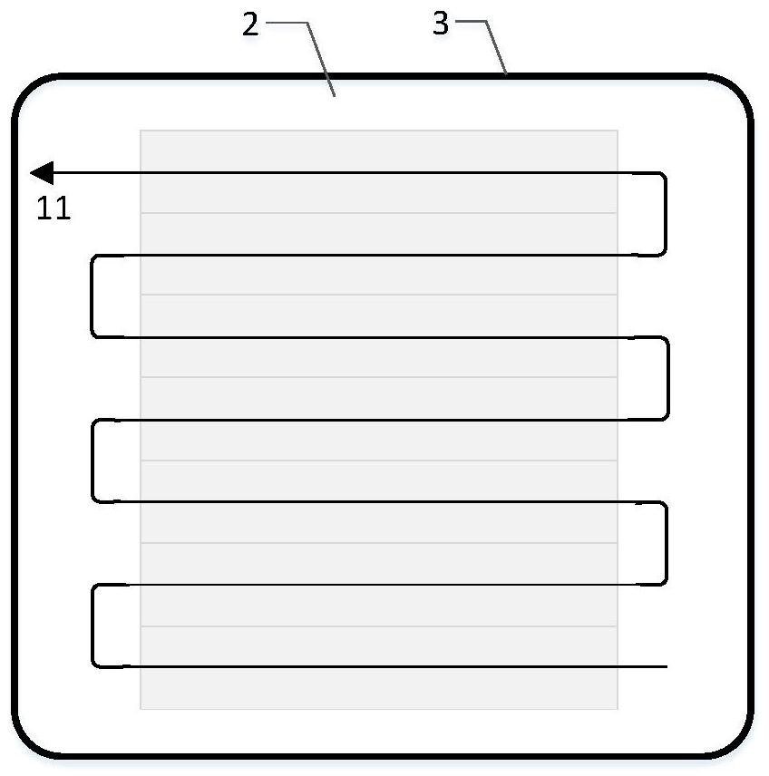
[0059] Step 1. Determine the optical fiber laying path 11 according to the monitoring area;
[0060] Step 2, the optical fiber laying path 11 is provided with a starting point 12, first to twelfth inflection points 13-24, and an end point 25;
[0061] Step 3. Start laying the optical fiber 27 on the original ice layer 2 along the direction of the starting point 12 of the optical fiber laying path 11. First, fix the optical fiber 27 at the starting point 12. The rounded cube ice cube 26 at the starting point 12 and the original ice layer 2 There is a gap at the edge of the contact surface between the two, and the optical fiber 27 is placed in the gap; after that, the optical fiber 27 is wound around the ice cube 26 for 10 turns along the gap, and water is dripped onto the optical fiber 27 wound around the ice cube 26 u...
Embodiment 3
[0068] The visual safety monitoring method of ice layer in natural ice rink based on distributed optical fiber sensing includes the following steps:
[0069] Step 1. The distributed optical fiber sensing demodulator 30 demodulates the strain signal measured by the optical fiber 27 and sends it to the monitoring host 31;
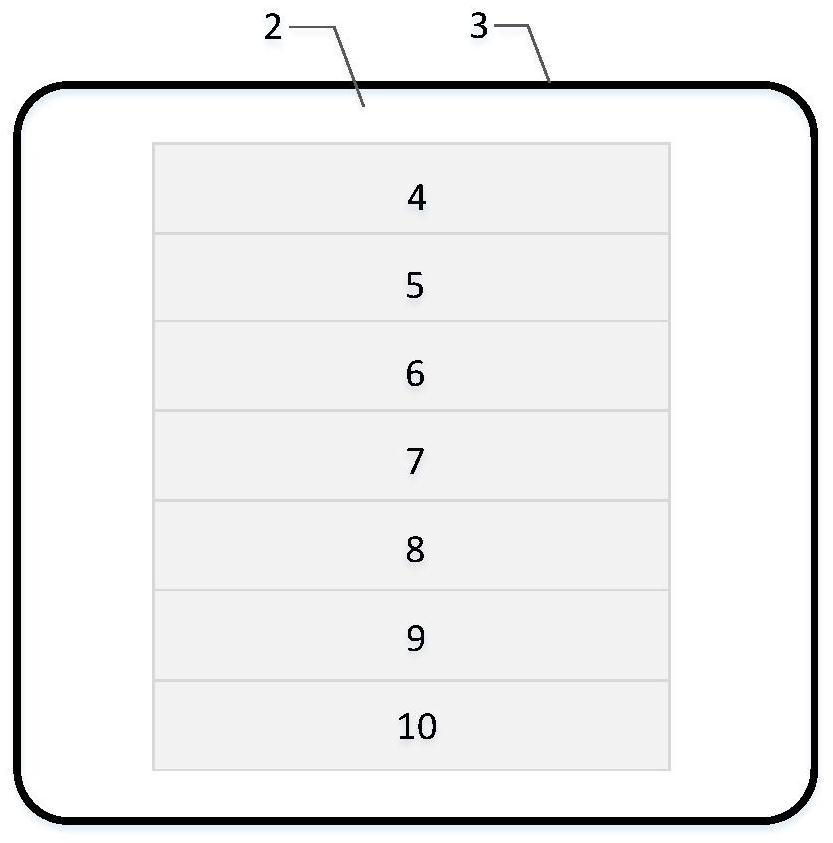
[0070] Step 2. The monitoring host 31 extracts the strain signal measured by the optical fiber 27 in the monitoring area 4-10, such as Figure 9 shown;
[0071] Step 3: The monitoring host 31 further converts the strain signal of the optical fiber 27 in the monitoring area 4-10 into a two-dimensional strain distribution map of the monitoring area 4-10, such as Figure 10 shown, where different color depths correspond to different strain values in the region. The larger the strain value, the higher the risk of ice damage and fracture safety hazards;
[0072] Step 4. When there is an area with a strain value greater than 100με, further safety inspection of...
PUM
 Abstract
Description
Claims
Application Information
 - Generate Ideas
- Intellectual Property
- Life Sciences
- Materials
- Tech Scout
- Unparalleled Data Quality
- Higher Quality Content
- 60% Fewer Hallucinations
Browse by: Latest US Patents, China's latest patents, Technical Efficacy Thesaurus, Application Domain, Technology Topic, Popular Technical Reports.
© 2025 PatSnap. All rights reserved.Legal|Privacy policy|Modern Slavery Act Transparency Statement|Sitemap|About US| Contact US: help@patsnap.com


