Flexible bulletproof blindage

A flexible, bunker technology, applied in protective equipment, offensive equipment, personnel protection equipment, etc., can solve the problems of increasing user load, inconvenient carrying, occupying storage space, etc. The effect of occupancy

Pending Publication Date: 2022-07-29
GUANGDONG JUNFENG SPECIAL EQUIP TECH DEV CO LTD
View PDF0 Cites 0 Cited by
  • Summary
  • Abstract
  • Description
  • Claims
  • Application Information

AI Technical Summary

Problems solved by technology

[0003] As a result, wearable bulletproof devices need to be worn in a series during use, and it takes a lot of time to wear them; while fixed bulletproof equipment, such as bulletproof shields, are rigid materials, so during use or storage state, it will correspond to the problems of inconvenient carrying and occupying storage space. In addition, the bulletproof shield needs to be grasped by hand during use, which increases the load of the user

Method used


Image

  • Flexible bulletproof blindage
  • Flexible bulletproof blindage
  • Flexible bulletproof blindage

Examples


Embodiment 1

[0045] see figure 2 , the invention discloses a flexible bulletproof bunker, the flexible bulletproof bunker comprises:

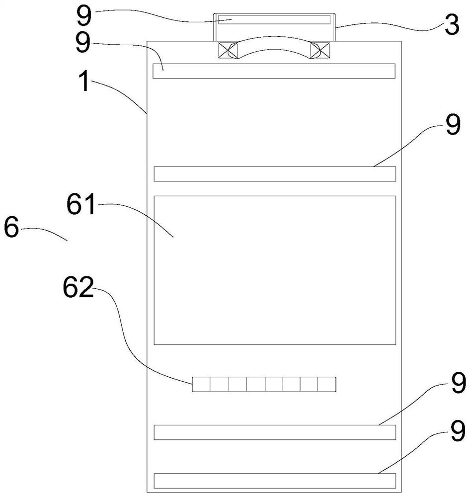
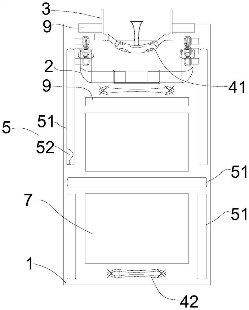
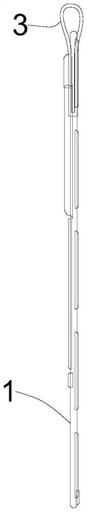
[0046] The flexible bulletproof body 1, specifically, includes a fiber jacket and a flexible bulletproof material filled in the fiber jacket. The flexible bulletproof body 1 is designed according to the human body. Preferably, the outer contour of the flexible bulletproof body 1 is a rectangle. Specifically, the flexible bulletproof body 1 One side is the bulletproof surface, and the bulletproof surface is used to prevent bullets;

[0047]The lanyard 2, specifically, the lanyard 2 is arranged on the back of the flexible bulletproof body 1 and is close to one of the short sides of the flexible bulletproof body 1. In particular, the lanyard 2 can be divided into two connecting straps, and the two connecting straps pass through The buckle is buckled and connected. The buckle is but not limited to this, such as a buckle, etc. The user can adjust the connectio...

Embodiment 2

[0062] The difference between the second embodiment and the first embodiment is that, refer to Figure 5 , the second embodiment also includes a splicing assembly 8. The splicing assembly 8 includes a first splicing part 81 and a second splicing part 82 that are detachably connected to each other. The first splicing part 81 and the second splicing part 82 are relatively arranged on the flexible bulletproof body 1 on both sides.

[0063] Specifically, the second splicing portion 82 includes a second splicing mother sticker, and the second splicing mother sticker is arranged on one side of the flexible bulletproof body 1 . In this embodiment, the second splicing mother sticker is arranged on one of the flexible bulletproof bodies 1 . on the long side.

[0064] The first splicing part 81 includes a first splicing mother sticker and a shielding sheet 811. The first splicing mother sticker and the second splicing mother sticker are oppositely arranged on the other long side of the...


PUM


Abstract

The invention discloses a flexible bulletproof blindage which comprises a flexible bulletproof body capable of being unfolded or folded. The hanging belt is arranged on the flexible bulletproof body and used for being worn when the flexible bulletproof body is unfolded and/or being carried when the flexible bulletproof body is rolled up. The flexible bulletproof main body has the flexible characteristic, the bulletproof main body is convenient to roll, the space occupancy rate of the rolled flexible bulletproof main body is reduced, and the flexible bulletproof shelter is convenient to carry and store; the hanging belt has the effects that in the using state, the flexible bulletproof body is hung on the neck or the shoulder of a user through the hanging belt, a convenient and rapid hanging function is provided for the flexible bulletproof body, and the hand grabbing load of the user is relieved in a wearing mode; in the non-use state, after the flexible bulletproof body is completely rolled, the flexible bulletproof blindage can be extracted or carried on the shoulder through the hanging belt, and the flexible bulletproof blindage is convenient to carry.

Description

technical field [0001] The invention relates to the field of protective equipment, in particular to a flexible bulletproof shelter. Background technique [0002] At present, bulletproof equipment includes wearable and fixed types. Wearable types include bulletproof vests, bulletproof pants or bulletproof caps, etc.; while fixed bulletproof equipment includes bulletproof shields. [0003] Therefore, the wearable bulletproof device needs to be worn in a series of times during use, which takes a lot of time to wear; while the fixed bulletproof equipment, such as the bulletproof shield, the bulletproof shield is a rigid material, so during use or storage In addition, the bulletproof shield needs to be grasped by hand during use, which increases the user's use load. SUMMARY OF THE INVENTION [0004] In order to overcome at least one of the deficiencies described in the prior art described above, the present invention provides a flexible bulletproof shelter. [0005] The techn...

Claims


Application Information

Patent Timeline
Patent Type & Authority Applications(China)
IPC IPC(8): F41H1/02
CPCF41H1/02
Inventor 陈飞王梓均
Owner GUANGDONG JUNFENG SPECIAL EQUIP TECH DEV CO LTD
Why Eureka
Try Eureka