
Mobile new energy automobile charging pile

A new energy vehicle and charging pile technology, applied in electric vehicles, charging stations, vehicle parts, etc., can solve the problems of charging cable damage, charging cable winding, knotting, reducing service life, etc., to increase service life, Avoid the effect of slipping out and breaking

Pending Publication Date: 2022-07-29
夏峰
View PDF0 Cites 0 Cited by
  • Summary
  • Abstract
  • Description
  • Claims
  • Application Information

AI Technical Summary

Problems solved by technology

[0003] The mobile new energy vehicle charging pile cannot reel up the automatic charging cable and place it reasonably, so that the charging cable is exposed outside the charging pile, causing the charging cable to often be entangled and knotted, and during long-term use, making the The charging cable often rubs against the ground, causing serious damage to the charging cable, which greatly reduces the service life of the charging cable and causes losses. In particular, it is necessary to fix the charging gun to prevent the charging gun from falling off and breaking. At the same time, it is necessary to remind the car owner to place the charging gun correctly. , when moving, most of the components inside the charging pile will reduce the service life due to excessive bumps and vibrations, so it is necessary to set a shock absorption function for the charging pile. For this reason, we propose a mobile new energy vehicle charging pile

Method used


Image

  • Mobile new energy automobile charging pile
  • Mobile new energy automobile charging pile
  • Mobile new energy automobile charging pile

Examples


Embodiment

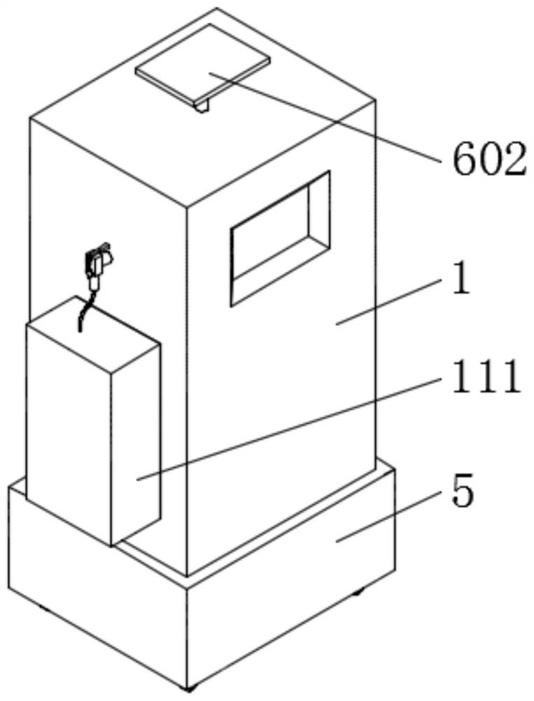
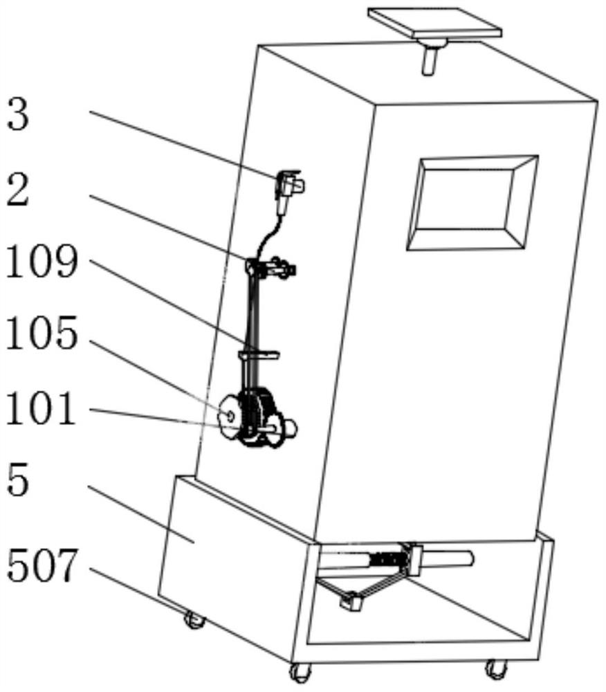
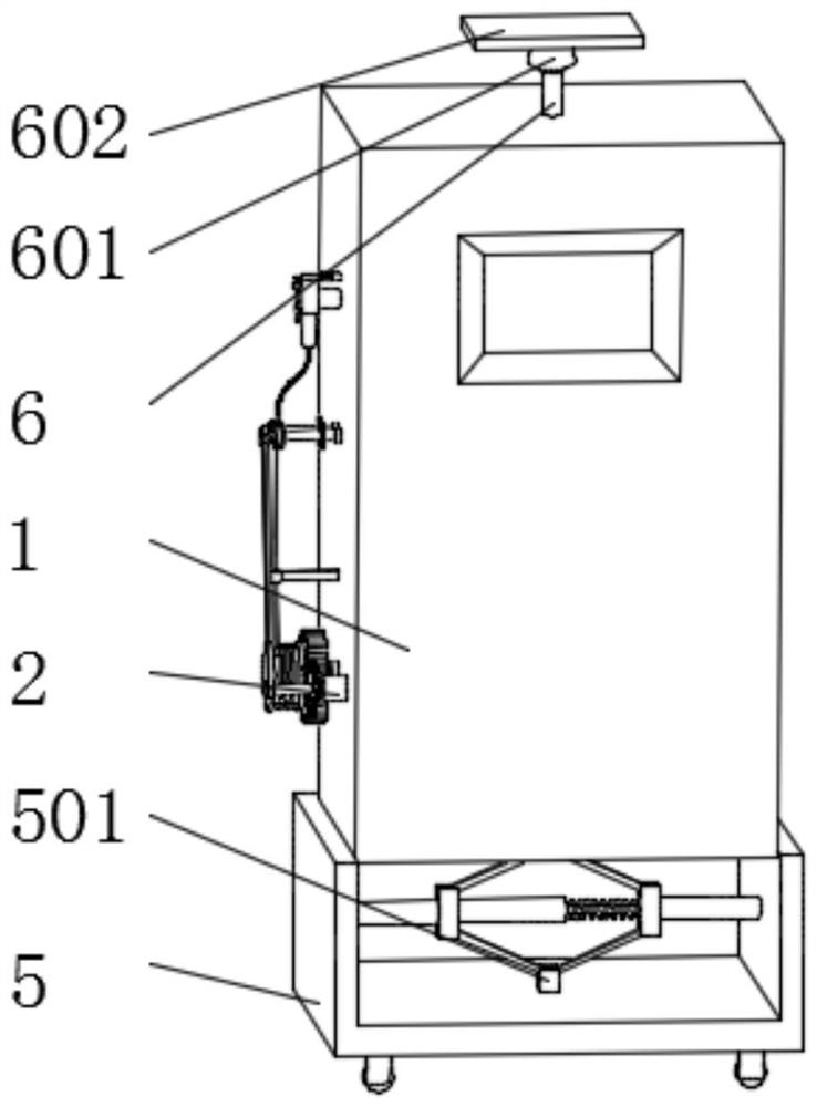
[0042] Example: Reference Figure 1-9 The shown mobile new energy vehicle charging pile includes a charging pile body 1, and the charging pile body 1 can be any metal new energy charging pile in the prior art.

[0043] A base 5 is installed on the charging pile body 1 in a movable socket, and universal wheels 507 are fixedly installed around the bottom of the base 5. One side of the charging pile body 1 is installed with a retractable conveying part, and the bottom of the charging pile body 1 is provided with a The shock absorber assembly, the retractable conveying part includes a retractable assembly and a conveying assembly, the retractable assembly includes a servo motor 101 fixedly installed on one side of the charging pile body 1, and the output end of the servo motor 101 is fixedly installed with a rotating shaft 102 through a coupling One end of the rotating shaft 102 is fixedly installed with a drive gear 103, one side of the charging pile body 1 is rotatably installed...


PUM


Abstract

The invention discloses a mobile new energy automobile charging pile, and relates to the field of automobile charging piles, the mobile new energy automobile charging pile is characterized in that a charging pile body is movably sleeved with a base, universal wheels are fixedly mounted on the periphery of the bottom of the base, and the charging pile body is provided with a retractable conveying part. When charging is needed, an intelligent operation screen is clicked to start a servo motor to drive a rotating shaft to rotate, the rotating shaft rotates to drive a driving gear to rotate, the driving gear rotates to drive a reduction gear to rotate, the reduction gear rotates to drive a rotating rod to rotate, and the rotating rod rotates to drive a rotating plate to rotate; the rotating plate rotates to drive the charging cable to be unwound, so that the charging cable is prevented from being pulled, the service life of the charging cable is prolonged, the two rotating rollers rotate to drive the two rotating rollers to rotate oppositely, the charging cable can be conveyed out of the protection box, and the charging cable is prevented from being wound and knotted in the protection box.

Description

technical field [0001] The invention relates to the field of vehicle charging piles, in particular to a mobile new energy vehicle charging pile. Background technique [0002] Charging piles generally provide two charging methods: conventional charging and fast charging. People can use a specific charging card to swipe the card on the human-computer interaction interface provided by the charging pile to perform operations such as corresponding charging methods, charging time, and cost data printing. The charging pile display can display data such as charging amount, cost, charging time and so on. [0003] The mobile new energy vehicle charging pile cannot roll up the automatic charging cable and place it reasonably, so that the charging cable is exposed outside the charging pile, resulting in frequent winding and knotting of the charging cable. The charging cable is often rubbed against the ground, causing serious damage to the charging cable, which greatly reduces the servi...

Claims


Application Information

Patent Timeline
Patent Type & Authority Applications(China)
IPC IPC(8): B60L53/31B60L53/18B65H75/44
CPCB60L53/31B60L53/18B65H75/4486
Inventor 夏峰申腾
Owner 夏峰
Learn More