
Mechanical arm and robot

A technology of manipulators and robots, applied in the field of robots, can solve problems such as difficult precise positioning and low movement precision of manipulators

Pending Publication Date: 2022-07-15
HUILING TECH ROBOTIC CO LTD
View PDF0 Cites 0 Cited by
  • Summary
  • Abstract
  • Description
  • Claims
  • Application Information

AI Technical Summary

Problems solved by technology

[0003] In order to solve the above problems, the present application provides a mechanical arm and a robot, which can solve the problems of low movement accuracy and difficulty in precise positioning of the mechanical arm

Method used


Image

  • Mechanical arm and robot
  • Mechanical arm and robot
  • Mechanical arm and robot

Examples


Embodiment 1

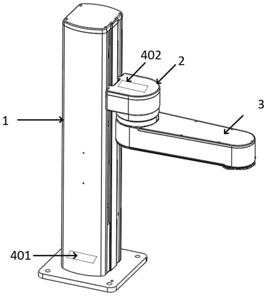
[0049] like figure 1 Shown is a schematic diagram of the overall structure of the robotic arm provided by this application, including a column assembly 1, a fixed seat assembly 2, an arm assembly 3, a first drive assembly 401 and a second drive assembly 402. One end of the fixed seat assembly 2 is movably connected to the On the column assembly 1, the other end of the fixed seat assembly 2 is movably connected with the arm body assembly 3, the first drive assembly 401 is used to drive the fixed seat assembly 2 to move on the column assembly 1, and the second drive assembly 402 is used to drive the arm body The assembly 3 rotates on the base assembly 2.

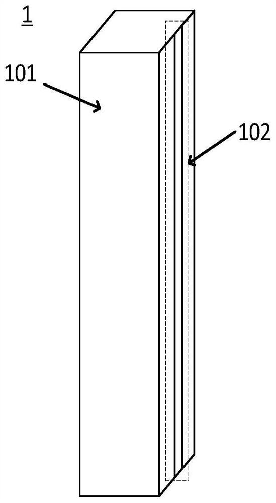
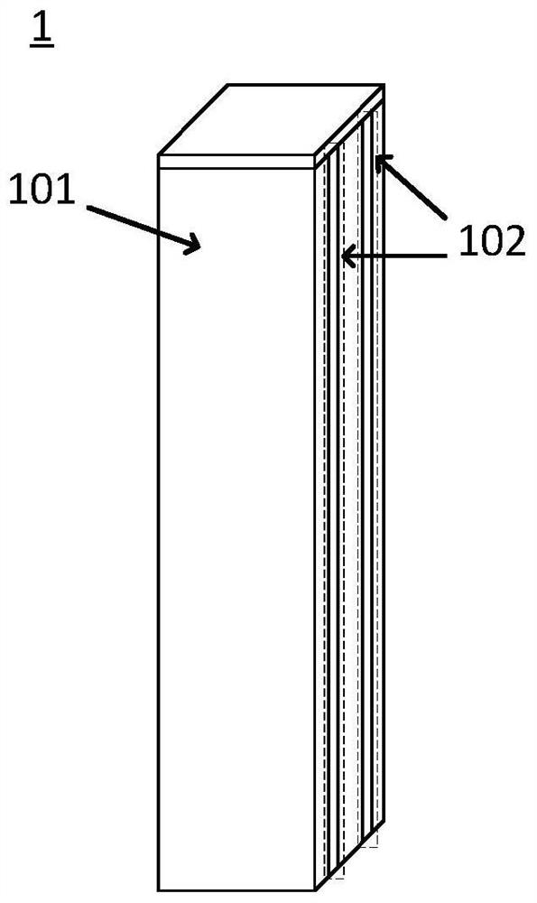
[0050] Wherein, the column assembly 1 provides a positioning direction for the mechanical arm, so that the fixed seat assembly 2 and the arm body assembly 3 can move in one direction along the column assembly 1, which improves the positioning accuracy in one direction, and in this way, The arm body structures of all levels in...

Embodiment 2

[0090] Based on the mechanical arm provided in the first embodiment, an embodiment of the present application further provides a robot, which includes the mechanical arm and the mechanical claw 5 provided in the first embodiment, and the mechanical claw 5 is movably connected with the arm body assembly 3 . The last-stage arm structure in the arm assembly 3 is movably connected to the mechanical claw 5, and the third drive assembly 403 in the last-stage arm structure is used to drive the mechanical claw 5 to rotate, and the mechanical claw 5 can be relative to the last stage. The arm structure rotates.


PUM


Abstract

The invention provides a mechanical arm and a robot, mainly relates to the field of robots, and can solve the problems that a mechanical arm is low in moving precision and difficult to accurately position. The mechanical arm comprises a stand column assembly, a fixing seat assembly, an arm body assembly, a first driving assembly and a second driving assembly, one end of the fixing seat assembly is movably connected to the stand column assembly, the other end of the fixing seat assembly is movably connected with the arm body assembly, and the first driving assembly is used for driving the fixing seat assembly to move on the stand column assembly; and the second driving assembly is used for driving the arm body assembly to rotate on the fixed seat assembly.

Description

technical field [0001] The invention relates to the field of robots, in particular to a mechanical arm and a robot. Background technique [0002] With the continuous development of robotic arm technology, it is widely used in various places because of its compact structure and high work efficiency. At present, the robotic arm usually uses a driving device to control the entire robotic arm, and cannot control the individual arm components. The positioning of the robot arm is precisely controlled, so that the movement accuracy of the robot arm in all directions is low, and it is difficult to accurately position the robot arm as a whole. SUMMARY OF THE INVENTION [0003] In order to solve the above problems, the present application provides a mechanical arm and a robot, which can solve the problems of low moving precision and difficulty in precise positioning of the mechanical arm. [0004] In a first aspect, the present application provides a robotic arm, the robotic arm in...

Claims


Application Information

Patent Timeline
IPC IPC(8): B25J18/00B25J19/00
CPCB25J18/00B25J19/00
Inventor 田军刘耀俊蔡国庆
Owner HUILING TECH ROBOTIC CO LTD
Learn More