
Method and filter device for filtering a liquid

A filter device and gas introduction device technology, applied in chemical instruments and methods, membranes, biological water/sewage treatment, etc., can solve the problems that the membrane has no flushing effect, does not include compensation inlet, and cannot flush the membrane, etc.

Pending Publication Date: 2022-06-24
MEMBION GMBH
View PDF8 Cites 0 Cited by
  • Summary
  • Abstract
  • Description
  • Claims
  • Application Information

AI Technical Summary

Problems solved by technology

[0010] In known methods and filtration devices, air initially flows from the geyser (gas introduction device) into the lateral openings, so that most of the liquid displaced by the air is displaced laterally from the module and is therefore not available for flushing the membranes
Also, depending on the size of the air pulse, a portion of the air escapes the module at the bottom of the module in a lateral direction and rises near the membrane filter, which means it is not used and has no flushing effect on the membrane
[0011] 在发明WO 2016 / 064466A(Koch Membrane Systems)、US 2009 / 0194477A1(AsahiKasai)、US 10179311B2(Sumitomo Electric)、CN 104519984BB(Samsung CheilIndustries)、KR 20190002717A(Mitsubishi Chemical)和WO 2011 / 028341A1(ZenonTechnology Partnership)的 In the background, gas introduction devices are disclosed which do not comprise compensating inlets and therefore can only be operated in a pulsed manner with a rather low gas volume supply

Method used


Image

  • Method and filter device for filtering a liquid
  • Method and filter device for filtering a liquid
  • Method and filter device for filtering a liquid

Examples


Embodiment Construction

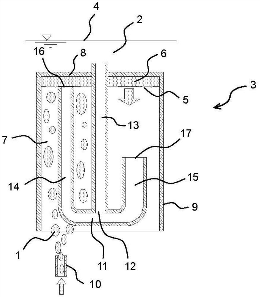
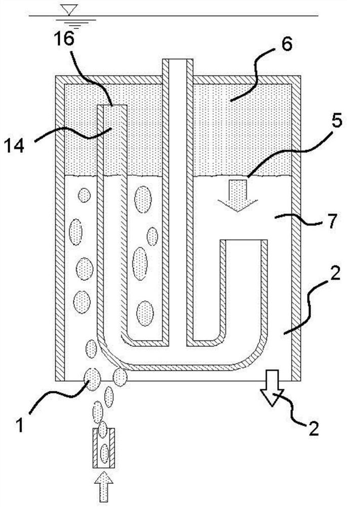
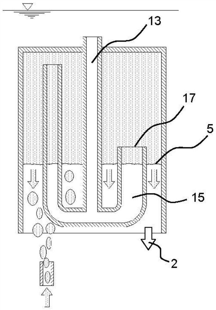
[0041] Figure 1a The process steps of the first method according to the invention are shown for introducing the gas 1 into the liquid 2 using the first gas introduction device 3 according to the invention shown in cross section.

[0042] The gas introduction device 3 comprises a gas volume 6 arranged below the surface 4 of the liquid 2 and defined by the liquid level 5 of the liquid 2 in a downward direction. The gas volume 6 is arranged in a gas collection chamber 7 defined by an upper wall 8 and side walls 9 . The gas 1 is introduced into the gas collection chamber 7 through a gas inlet 10 installed below and separated from the gas collection chamber 7 , filling the gas volume 6 and causing the liquid level 5 of the liquid 2 to drop. Therefore, the liquid 2 in the gas collection chamber 7 is displaced successively by the inflowing gas 1 in the downward direction at this point in time, and is replaced by the gas 1 .

[0043] The gas introduction device 3 according to the in...


PUM


Abstract

The invention relates to a method for filtering a liquid through a membrane (76) in a membrane filter (64) immersed in the liquid. In order to clean the membrane (76), a gas introduction device (63) is used to introduce a gas from below into the membrane filter (64) in the form of continuous pulses, in which, for each pulse, first a gas volume arranged below the liquid surface and defined at the bottom by the liquid level is filled with the gas, and then the gas volume is filled with the gas. The gas (1) simultaneously displaces the liquid from the top towards the bottom and exits from the gas lift channel (70) until the liquid level drops below the inlet cross-section (72) of the gas outflow channel (73), and then the gas sequentially passes downward through the gas lift channel and from below through a deflection portion (71) adjacent to the gas lift channel, the gas volume flows upward from above through an inlet cross-section (72) and through a gas outflow channel (73) adjoining the inlet cross-section, and then to the surface. The invention also relates to a filter device (84) for carrying out such a method, comprising a membrane filter (64) for filtering a liquid through a membrane and a gas introduction device arranged below the membrane. The purpose of the present invention is to improve the cleaning effect of introduced air. This is achieved by the housing (80) laterally surrounding the membrane (76) and abutting the gas introduction means (63) on top.

Description

technical field [0001] The present invention relates to a method for filtering liquid in a membrane filter immersed in liquid, wherein the membrane filter comprises a membrane. To clean the membrane, a gas introduction device is used to introduce gas into the membrane filter from below in successive pulses by filling a gas volume arranged below the liquid surface and defined at the bottom by the liquid level initially filled with gas , where the gas simultaneously displaces the liquid from the top down and exits the gas lift channel until the liquid level drops below the inlet cross-section of the gas outflow channel, then the gas passes down the gas lift channel and abuts at the bottom of the gas lift channel The deflected portion of the gas lift channel flows upward through the inlet cross-section and flows out of the gas volume from above through a gas outflow channel adjoining the inlet cross-section at the top of the gas inlet cross-section and then to the liquid surface....

Claims


Application Information

Patent Timeline
Patent Type & Authority Applications(China)
IPC IPC(8): B01D63/02B01D63/04B01D65/02B01D65/08C02F3/12C02F3/20
CPCB01D63/02B01D63/04B01D65/02B01D65/08C02F3/1273C02F3/208B01D2315/06B01D2321/185Y02W10/10B01D63/06B01D2313/26
Inventor 克劳斯·沃森卡尔迪尔克·沃尔梅林
Owner MEMBION GMBH
Learn More