
Pose measuring plate and method for automatically operating universal centrifugal machine through mechanical arm

A technology of pose measurement and measurement board, which is applied in the direction of centrifuges, measuring devices, optical devices, etc., can solve the problem of high cost, achieve cost saving, improve operation accuracy and efficiency, and facilitate application

Active Publication Date: 2022-06-24
UNIV OF SCI & TECH OF CHINA
View PDF6 Cites 0 Cited by
  • Summary
  • Abstract
  • Description
  • Claims
  • Application Information

AI Technical Summary

Problems solved by technology

This kind of centrifuge that achieves rotor positioning through hardware is usually highly customized, and often needs to be manufactured in advance, which is costly and cannot be directly applied to existing ordinary laboratory centrifuges in a modular manner.
[0004] At present, there is no method for accurately measuring the rotor pose of a general-purpose centrifuge at low cost without modifying the internal hardware of the general-purpose centrifuge.

Method used


Image

  • Pose measuring plate and method for automatically operating universal centrifugal machine through mechanical arm
  • Pose measuring plate and method for automatically operating universal centrifugal machine through mechanical arm
  • Pose measuring plate and method for automatically operating universal centrifugal machine through mechanical arm

Examples


Embodiment

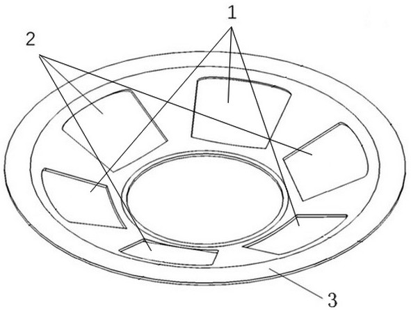
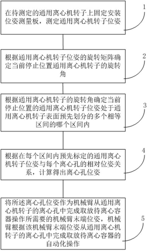
[0086] like figure 2 As shown in the figure, an embodiment of the present invention provides a method for automatically operating a universal centrifuge by a robotic arm. Before performing visual measurement and positioning on the centrifuge rotor, a pose measurement board is fixedly installed on the upper surface of the centrifuge rotor. The shape of the plate is the same as that of the upper surface of the centrifuge rotor, which can be tightly fitted on the upper surface of the centrifuge rotor. The rotor remains relatively static, that is, the two rotate synchronously; there are three through holes and three label installation grooves on the surface of the pose measurement board, and the through holes and the label installation grooves are spaced from each other and evenly distributed in a ring; the three label installation grooves Labels are placed in the slots, and each label has different predetermined graphic information;

[0087] In practical applications, the camera ...


PUM


Abstract

The invention discloses a pose measuring plate and a method for automatically operating a universal centrifuge through a mechanical arm, and the method comprises the steps: fixedly installing the pose measuring plate with three labels on a rotor of the universal centrifuge to be measured, measuring the pose of the rotor of the universal centrifuge, determining a rotation angle, and determining which interval the rotor is located in; and according to the relation between the position and posture of the rotor of the universal centrifugal machine calibrated in advance in each interval and the relative position and posture of each centrifugal hole, the position and posture of the centrifugal hole are calculated, and the position and posture of the tail end of the mechanical arm are obtained according to the position and posture of the centrifugal hole. And the mechanical arm completes automatic operation of taking and placing the container to be centrifuged from the centrifugal hole of the rotor of the general centrifugal machine according to the tail end pose of the mechanical arm. The method is suitable for the mechanical arm to operate most centrifugal machines, hardware transformation does not need to be carried out on the interiors of the centrifugal machines, the stopping positions of the rotors before and after centrifugation do not need to be changed, and the method can be universally used for automatic operation of the mechanical arm on the universal centrifugal machines.

Description

technical field [0001] The invention relates to the field of automatic operation of centrifuges, in particular to a method for automatic operation of a general centrifuge by a posture measuring plate and a mechanical arm. Background technique [0002] Under the conditions of the intelligent laboratory, it is necessary to realize the automatic operation of the centrifuge by the robotic arm, mainly by placing the container to be centrifuged into the centrifuge hole on the centrifuge rotor, and taking it out after the centrifugation is completed. Before and after centrifugation, since the position where the rotor stops is random, in order to realize automatic operation, it is first necessary to be able to automatically detect or locate the current rotor posture, so that the robotic arm can automatically put the container to be centrifuged in or out of the centrifuge hole. [0003] At present, most of the centrifuges with automatic positioning are built on the basis of a large n...

Claims


Application Information

Patent Timeline
IPC IPC(8): B04B13/00B04B11/04G01B11/00
CPCB04B13/003B04B11/04G01B11/00B04B2011/046
Inventor 尚伟伟张旭春张飞江俊丛爽
Owner UNIV OF SCI & TECH OF CHINA
Learn More