
Static pressure sliding block and static pressure guide rail

A technology of static pressure and slider, applied in the direction of bearing, shaft and bearing, mechanical equipment, etc., can solve the problem of low rigidity of static pressure guide rail

Pending Publication Date: 2022-06-03
湖南宇环精密制造有限公司
View PDF0 Cites 0 Cited by
  • Summary
  • Abstract
  • Description
  • Claims
  • Application Information

AI Technical Summary

Problems solved by technology

[0003] Based on this, it is necessary to provide a hydrostatic slider for the technical problems that the pressure oil flow rate in the oil delivery tank in the hydrostatic guide rail is small and the stiffness of the entire hydrostatic guide rail is low.

Method used


Image

  • Static pressure sliding block and static pressure guide rail
  • Static pressure sliding block and static pressure guide rail
  • Static pressure sliding block and static pressure guide rail

Examples


Embodiment Construction

[0034] In order to make the above objects, features and advantages of the present invention more clearly understood, the specific embodiments of the present invention will be described in detail below with reference to the accompanying drawings. In the following description, numerous specific details are set forth in order to provide a thorough understanding of the present invention. However, the present invention can be implemented in many other ways different from those described herein, and those skilled in the art can make similar improvements without departing from the connotation of the present invention. Therefore, the present invention is not limited by the specific embodiments disclosed below.

[0035] In the description of the present invention, it should be understood that the terms "center", "longitudinal", "lateral", "length", "width", "thickness", "upper", "lower", "front", " Back, Left, Right, Vertical, Horizontal, Top, Bottom, Inner, Outer, Clockwise, Countercl...


PUM


Abstract

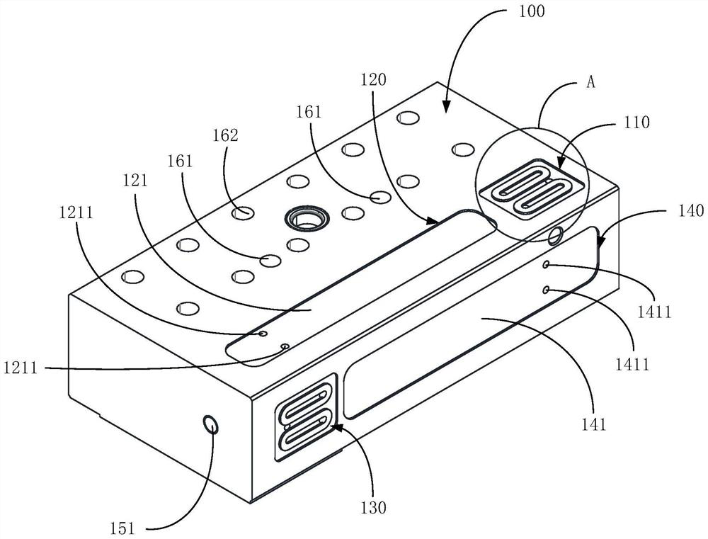
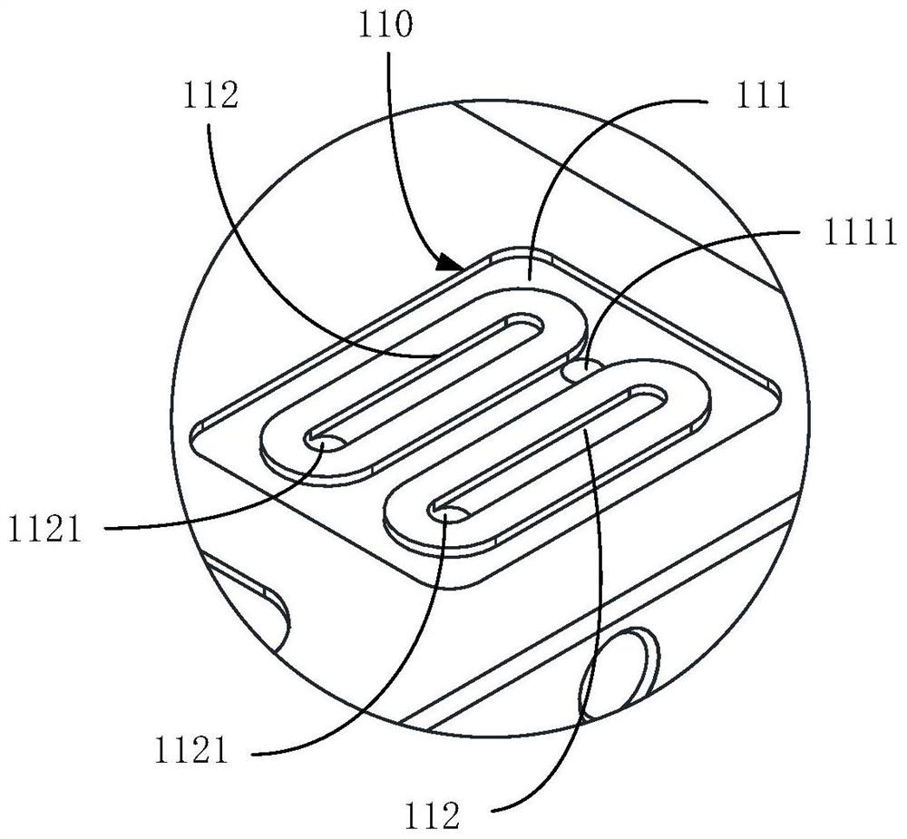
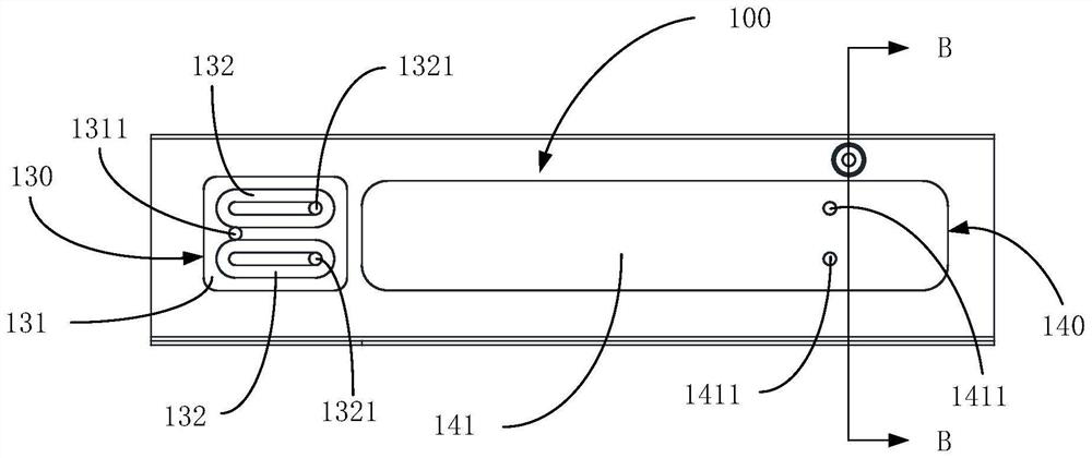
The invention relates to a static pressure sliding block which is provided with a first throttling device and a first pressure bearing piece, the first throttling device abuts against a lower guide rail, and the first pressure bearing piece abuts against an upper guide rail. Or the first throttler abuts against the upper guide rail, and the first pressure-bearing piece abuts against the lower guide rail. The first throttler is provided with a first pressure oil groove, the first pressure oil groove is communicated with an external oil conveying channel, and pressure oil can be pumped into the first pressure oil groove; the first pressure oil groove protrudes towards the interior of the groove cavity along the bottom wall of the first pressure oil groove and forms a first oil conveying groove of an annular hollow structure, and pressure oil can flow into the first oil conveying groove from the first pressure oil groove; the first pressure-bearing piece is provided with a first pressure-bearing cavity, and the first oil conveying groove is communicated with the first pressure-bearing cavity; pressure oil in the first oil conveying groove can flow between the first pressure bearing cavity and the upper guide rail or between the first pressure bearing cavity and the lower guide rail. Due to the fact that the inflow amount of the pressure oil in the first oil conveying groove is increased, and the leakage amount is reduced, the flow amount flowing into the first pressure bearing cavity is large, and the rigidity of the whole static pressure guide rail is high.

Description

technical field [0001] The invention relates to the technical field of precision machining, in particular to a static pressure slider and a static pressure guide rail. Background technique [0002] Hydrostatic guideways are widely used in precision machine tools due to their low friction and good oil film vibration resistance during movement. However, in the prior art, the oil conveying groove and the pressure oil groove of the restrictor on the hydrostatic guide rail are both straight cylinder structures, and are arranged side by side with each other. Therefore, when the pressure oil in the pressure oil tank is input to the oil tank, one side of the oil tank is fed with the pressure oil in the pressure tank, but the other three sides will overflow the pressure oil in the oil tank to the outer circumference of the oil tank, and then The flow rate of the pressure oil in the oil tank is small, and the rigidity that the entire hydrostatic guide rail can bear is low. SUMMARY ...

Claims


Application Information

Patent Timeline
IPC IPC(8): F16C32/06
CPCF16C32/0659F16C32/0655
Inventor 李锡晗李戈叶培仓
Owner 湖南宇环精密制造有限公司
Learn More